3-19
DSR-2000A/2000AP
CN901
CN902
CN505
CN501
CN504
CN503
CN502
CN500
CN605
CN604
CN603
CN602
CN601
CN608
CN607
CN606
CN703
CN704
CN702
CN701
Screws
PWH3 x 6
Screws
PWH3 x 6
Screws
PWH3 x 6
MB-859 board
Flexible
card wires
Harness
connectors
Screws
PWH3 x 6
Screws
PWH3 x 6
Bottom
panel
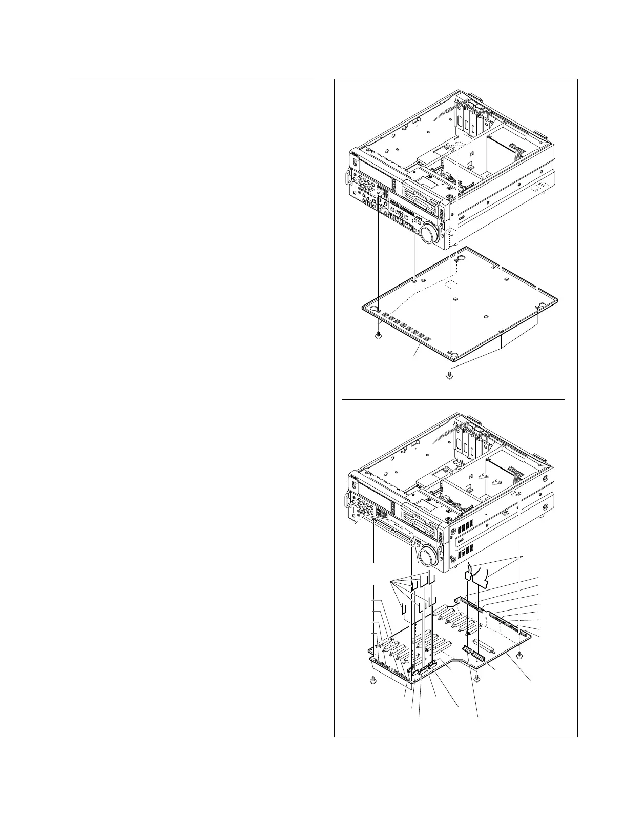
Removal/Reattachment of the MB-859
(1) Remove the APR-45 board, VPR-62A board, DPR-
136A board, SY-278A board and SV-212 board.
(Refer to Section 3-5-1.)
(2) Remove the EX-752 board. (Refer to this section
Removal/ Reattachment of the EX-752 board.)
(3) Disconnect the harnesses from the two connectors
(CN901 and CN902) of the MB-859 board and also
disconnect the flexible card wire from the connector
(CN505).
(4) Remove the bottom panel. (Refer to Section 3-3.)
(5) Disconnect the three flexible card wires from the
connectors (CN500, CN501, CN502, CN503 and
CN504) of the MB-859 board.
(6) Remove the 10 screws to remove the MB-859 board.
(7) Reset the MB-859 board to the unit aligning properly
the connectors of the MB-859 board (CN601, CN602,
CN603, CN604, CN605, CN606, CN608, CN701,
CN702, CN703 and CN704) to the correspondent
connectors on the unit.
n
Use care not to bend the connector pins.
(8) Reattach the MB-859 board in the reverse order of the
removing steps (1) to (6).