3-21
DSR-2000A/2000AP
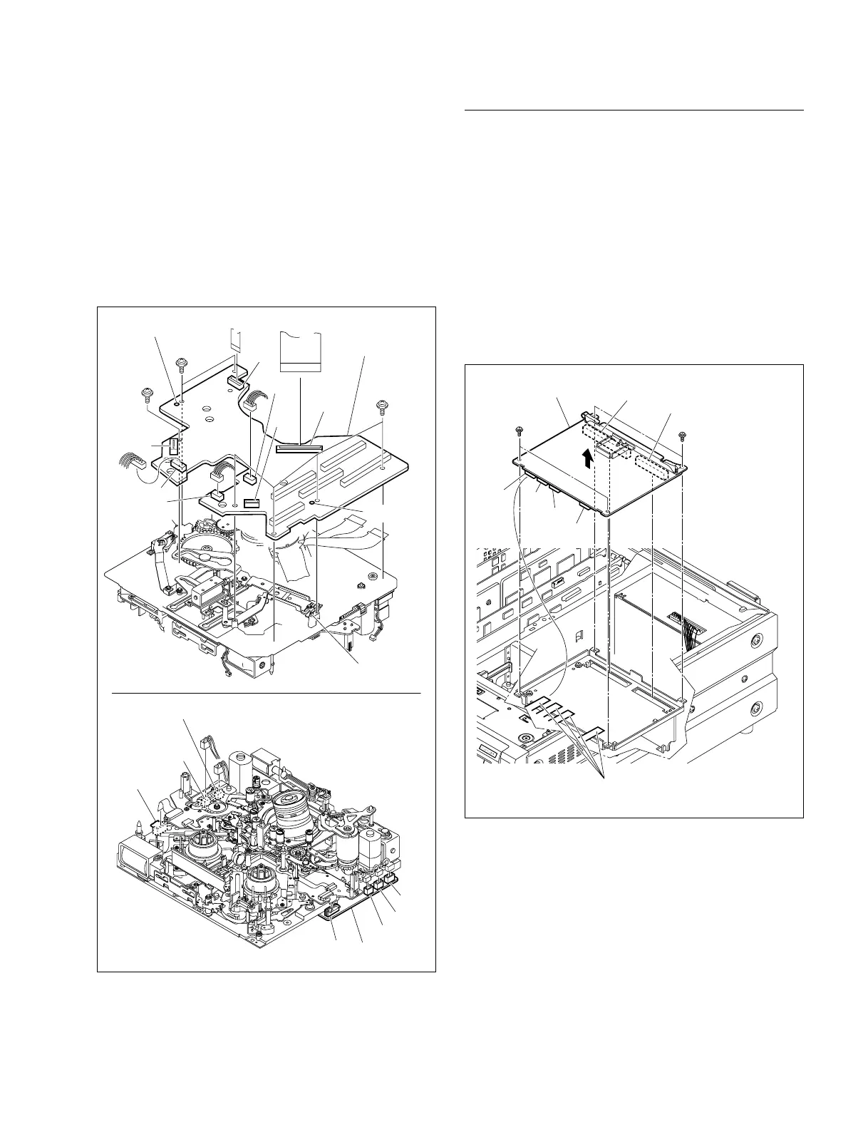
CN2
CN5
CN3
CN4
CN19
CN12
CN13
MS-64 board
CN1
CN8
CN7
CN6
CN9
CN11
CN10
MS-64 board
Positionin
hole
Positioning pin
Positioning
pin
Positioning hole
Screws
B2 x 4
Screws
B2 x 4
Screw
B2 x 4
RP-111 board
Screws
PWH3 x 6
CN4
CN3
CN2
CN1
Screws
PWH3 x 6
Flexible card wires
CN301
CN302
(8) Release the connection of connectors on the MS-64
board (CN1, CN2, CN3, CN4, CN5, CN6, CN7, CN8,
CN9, CN10, CN11, CN12, CN13 and CN19).
(9) Remove the seven screws (B2 x 4) to remove the MS-
64 board.
(10)Fit the two positioning holes of the MS-64 board on
the positioning pins on the MD chassis respectively
and fix the board with the seven screws.
(11)Reattach the MS-64 board in the reverse of the
removing steps (1) to (9).
Removal/Reattachment of the RP-111 board
(1) Remove the top and bottom panels.
(Refer to Section 3-3.)
(2) Disconnect the four flexible card wires from the
connectors of the RP-111 board (CN1, CN2, CN3, and
CN4).
(3) Remove the four screws (PWH3 x 6).
(4) Release the connection of the two connectors (CN301,
CN302) on RP-111 board to remove the RP-111
board.
(5) Reattach the RP-111 board in the reverse order of
removing steps (1) to (4).