3-24
DSR-2000A/2000AP
Control frame assembly
Indentation
SW-11/11P board
CN702
Screw
PWH3 x 6
Screw
PWH3 x 6
Notch of
chassis
Notch of
chassis
CN701
(mother board)
CN703
CN703
CN702
CN701
CN704
CN704
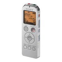
Removal/Reattachment of the SW-11/11P board
(1) Disconnect the three flexible card wires from the
connectors (CN710, CN720, CN730) of the SW-11/
11P board with the control panel brought to the lateral
position. And remove the FPC holder.
(2) Remove the two screws (PWH 3 x 6) to remove the
sub panel cover.
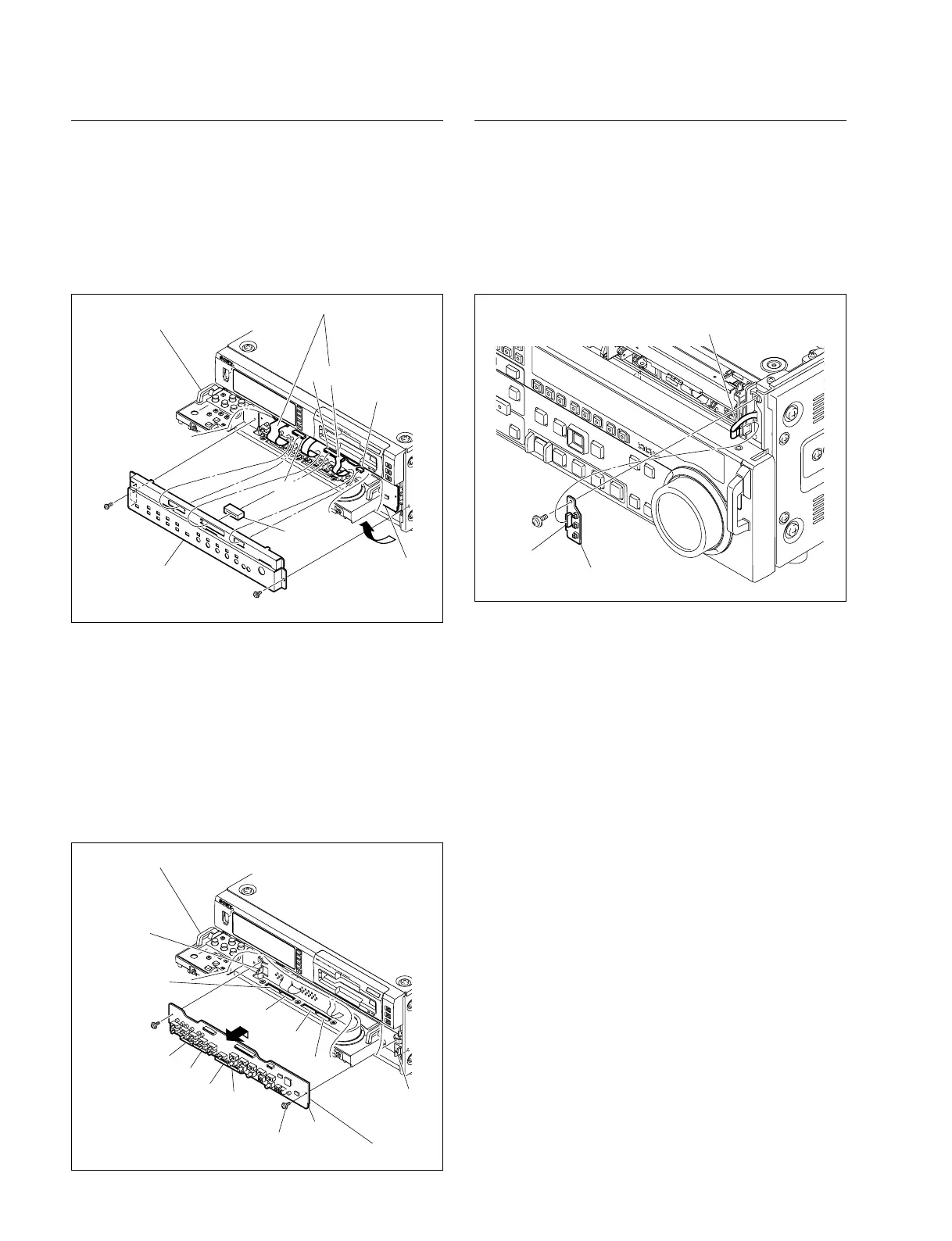
(3) Remove the two screws (PWH 3 x 6) and remove the
SW-11/11P board upward.
(4) Fit the indentation of the SW-11/11P board with the
notch of the chassis so as to connect the connectors of
SW-11/11P board (CN701, CN702, CN703 and
CN704) to the connectors of the motherboard (CN701,
CN702, CN703 and CN704).
(5) Reattach the SW-11/11P board in the reverse order of
the removing steps (1) to (3).
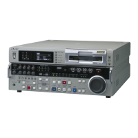
Removal/Reattachment of the SW-17 board
(1) Remove the front panel. (Refer to Section 3-3.)
(2) Disconnect the flexible card wire from the connector
(CN730) of the SW-17 board.
(3) Remove the screw to remove the SW-17 board.
(4) Reattach the SW-17 board in the reverse order of the
removing steps (1) to (3).
CN730
SW-17 board
Flexible card wire
Screw
PWH3 x 6
FPC holder
CN730
CN710
CN720
Control frame assebly
SW-11/11P board
Sub panel cover
Screw
PS3 x 6
Screw
PWH3 x 6
Flexible card wires