3-25
DSR-2000A/2000AP
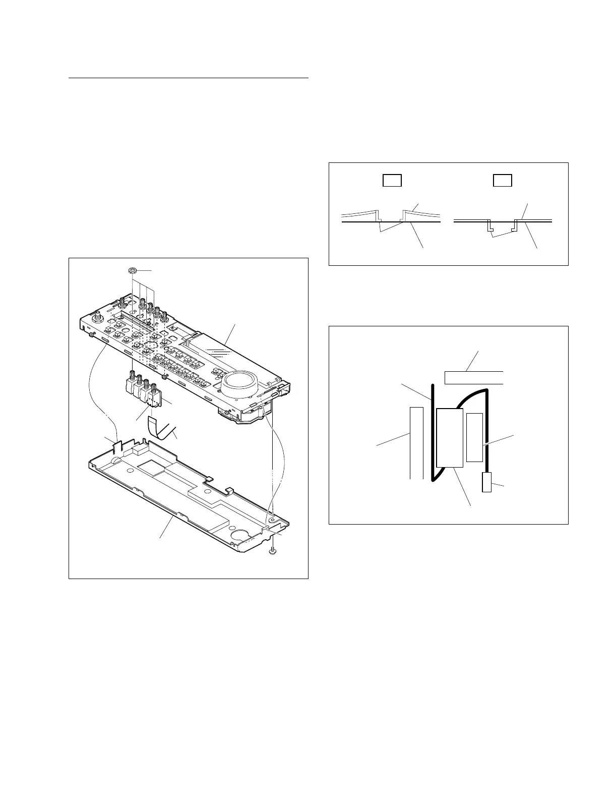
Removal/Reattachment of the VR-259 board
(1) Remove the control frame assembly. Refer to this
section Removal/Reattachment of the HP-99 board,
steps (1) to (4).
(2) Remove the screw (PWH3 x 6) and release the two
claws from the rear side, and remove the KY cover.
(3) Disconnect the flexible card wire from the connector
(CN1) of the VR-259 board.
(4) Remove the four nuts to remove the VR-259 board.
n
Support the VR-259 board from the rear side when
removing the nuts.
Screw
PWH3 x 6
Claw
KY cover
Flexible card wire
Attached nuts
Claw
Control frame assembly
VR-259 board
CN1
(5) Reattach the VR-259 board in the reverse order of the
removing steps (1) to (4).
m
. When reattaching the KY cover, check that the
portion A is inserted to the control frame assembly
correctly.
. When connecting the flexible card wire to the
connector (CN710) on the KY-452 board, attach the
ferrite core as following figure.
NG OK
Portion A
Portion A
Control frame assembly Control frame assembly
KY cover KY cover
CN710
Portion A
Flexible card wire
Ferrite core
Control frame assembly
KY cover