6-27
DSR-80/80P/60/60P
6-18. RING ROLLER REPLACEMENT
Note : When attaching/removing of threading
ring assembly, be careful not to touch
the peripheral tape guides, drum and
capstan shaft.
Removal
1. Remove the gear box assembly.
(Refer to section 6-12.)
2. Remove the S arm assembly.
(Refer to section 6-23.)
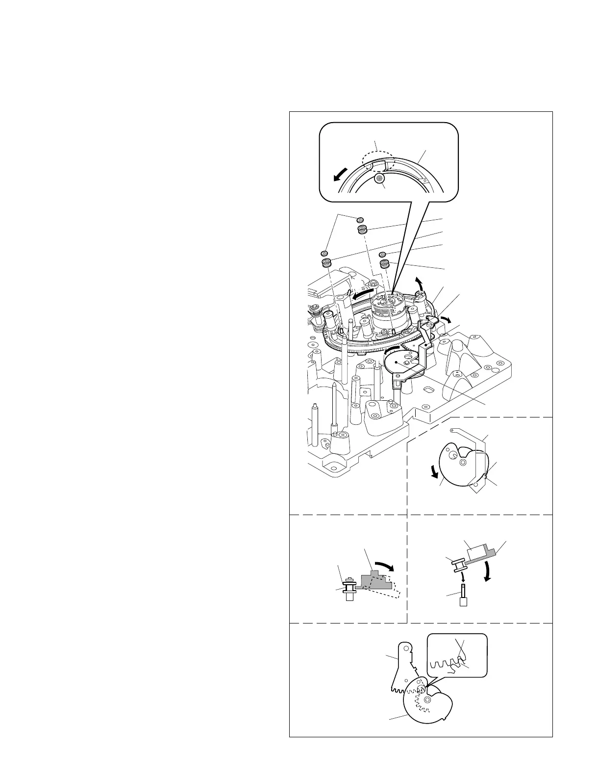
3. Revolve the cam gear in the direction of arrow D
by hand until the roller block of the T drawer
arm is locked with the stepped portion of the cam
gear. (Fig.-2)
4. Revolve the threading ring with hand in the
direction of arrow A until the recessed portion
comes to “a” position of the ring roller.
(Refer to Fig.-1)
5. Remove the stop washer 1.5 of the ring roller “a”.
6. While lifting the threading ring slightly up in the
direction of arrow C, remove the ring roller “a”.
7. While pressing the T drive arm assembly in the
direction of arrow B, remove the threading ring
assembly from the grooves of the ring rollers “b”
and “c”. (Fig.-3)
8. Remove the two stop washers 1.5 from the ring
roller “b” and “c”, and remove the ring roller.
Attachment
9. Put the new ring rollers b and c through the
shafts of threading ring, attach the two stop
washers 1.5 to them.
10.Assemble the parts by reversing the removal
procedure of step 8.
11.While inserting the new ring roller “a” into the
recessed portion of the threading ring assembly,
insert the ring roller “a” into the shaft. (Fig.-4)
12.Attach the stop washer 1.5 to the ring roller “a”.
13.Unlock the roller of the T drawer arm.
14.Confirm that the cam gear of the T drawer arm of
the T drive arm assembly is angaged correctly.
(Fig.-5)
15. Attach the S arm assembly. (Refer to section 6-23.)
16.Confirm that the S arm assembly and the T
drawer arm work correctly when the threading
ring assembly is turned with hand.
17.Attach the gear box assembly.
(Refer to section 6-12.)
C
A
D
B
Fig.-3
Fig.-4
Fig.-2
Fig.-1
Stop washers 1.5
Ring roller a
Threading ring assembly
Treading ring
assembly
T drive arm assembly
Dents
Threading ring
assembly
Dents
Ring roller a
Groove
Treading ring
assembly
Ring roller b, c
Shaft
Stepping
portion
Roller
Cam gear
T drawer arm
Cam gear
Ring roller c
Ring roller b
Stop washer 1.5
Ring roller a
Tooth
root B
Tooth A
Cam gear
T drive arm assembly
Fig.-5
T drawer arm
A
D


 To Next Page