1
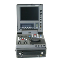
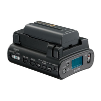
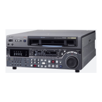
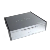
DSR-80/80P/60/60P
TABLE OF CONTENTS
1. OPERATING INSTRUCTIONS
The DSR-60/60P manual will be available as a supplement shortly.
2. INSTALLATION
2-1. Installation Procedure ..................................................................................... 2-1
2-2. Operational Environment ............................................................................... 2-1
2-3. Operating Voltage .......................................................................................... 2-1
2-4. Installation Space ........................................................................................... 2-2
2-5. Supplied Accessories ...................................................................................... 2-2
2-6. Optional Accessories ...................................................................................... 2-2
2-7. Rack Mounting ............................................................................................... 2-3
2-8. Connection of Editing Equipment,
and Input/Output Signals of Connectors ........................................................ 2-5
2-8-1. Connection of Editing Equipment .......................................................... 2-5
2-8-2. Matching Connectors.............................................................................. 2-9
2-8-3. Input/Output Signals of the Connectors ............................................... 2-10
2-9. Installation Setup and Adjustment ............................................................... 2-13
2-9-1. Switch Settings on the Connector Panel............................................... 2-13
2-9-2. Setting on the Front Panel Unit ............................................................ 2-13
2-9-3. On-board Switch Setting ...................................................................... 2-14
2-9-4. System Adjustment After Installation .................................................. 2-16
2-9-5. Connection of Editor Controller ........................................................... 2-16
2-10.Setup Check Sheets ...................................................................................... 2-18
3. SERVICE OVERVIEW
3-1. Location of Main Parts ................................................................................... 3-1
3-1-1. Location of Printed Circuit Boards......................................................... 3-1
3-1-2. Location of Main Mechanical Parts ....................................................... 3-2
3-1-3. Location of Sensors (1) .......................................................................... 3-4
Location of Sensors (2) .......................................................................... 3-5
3-2. Functions of Record Proof Hole and Record Proof Plug of Cassette ............ 3-6
3-3. Error Messages ............................................................................................... 3-7
3-3-1. Alarm Display ........................................................................................ 3-7
3-3-2. Error Codes............................................................................................. 3-9
3-4. Removal and Attachment of the Cabinet ..................................................... 3-22
3-5. Removal and Attachemt of the Cassette Compartment................................ 3-23
3-6. Removal of the Switching Regulator ........................................ 3-24
3-6. Removal of the Switching Regulator ........................................ 3-25
3-7. Replacement of the Fuse .............................................................................. 3-26
3-8. Extension Board ........................................................................................... 3-26
3-9. Removal and Attachment of the Boards....................................................... 3-27
3-9-1. Removal of the Card Boards ................................................................ 3-27
3-9-2. Removal of the CP-276B Board ................................... 3-28
3-9-2. Removal of the CP-276A Board ................................... 3-29
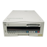
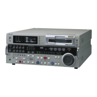
DSR-80/80P
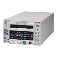
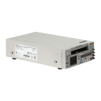
DSR-60/60P
DSR-60/60P
DSR-80/80P
http://getMANUAL.com
 Loading...