3-22
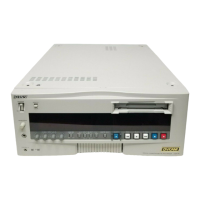
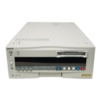
DSR-80/80P/60/60P
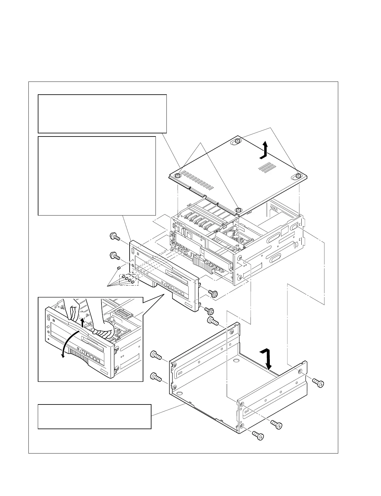
3-4. REMOVAL AND ATTACHMENT OF THE CABINET
Be sure to remove the cabinet after turning off the power switch.
Top panel
1. Loosen the four fixing screws. Move the
top panel in the direction of arrow and remove it.
(The screws have the drop-protector so that they
cannot fall out of the upper cover.)
Front panel
1. Remove the top panel.
2. Remove the controls of HEADPHONE and
VOLUME.
3. Remove the two fixing screws (PWH 3x6) in
the right and left. Insert a finger tip into the
clearance between the front panel and chassis
as shown in Fig.-1. While lifting up the edges
of the panel in teh direction of arrow A, open
the edges of the panel in the direction of
arrow B, and remove the front panel.
A
B
Fig.-1
U case
1. Remove the six fixing screws (B 4x6) in the
direction of arrow and remove the U case.
B 4x6
PWH 3x6
PWH 3x6
Fixing screw
(with drop-protector)
Fixing screw
(with drop-protector)
Volume
For
DSR-80/80P only
PWH 3x6
B 4x6
B 4x6
B 4x6


 To Next Page