7-12
DSR-80/80P/60/60P
7-6. RF SWITCHING POSITION ADJUSTMENT
Be sure to perform the RF switching position adjustment whenever the TAPE PASS ADJUSTMENT (refer to section 7-2)
is performed.
This adjustment can be performed by the AUTO adjustment procedure and the MANUAL adjustment procedure.
Perform the AUTO adjustment first. If the RF switching position adjustment cannot be completed by the AUTO
adjustment, perform the MANUAL adjustment.
Preparation
Connect the video monitor to the VIDEO OUTPUT 2 connector on the rear panel to show the characters on the display.
Tools
Alignment tape, XH5-1A : 8-967-999-21 (NTSC)
XH5-1AP : 8-967-999-25 (PAL)
[AUTO Adjustment]
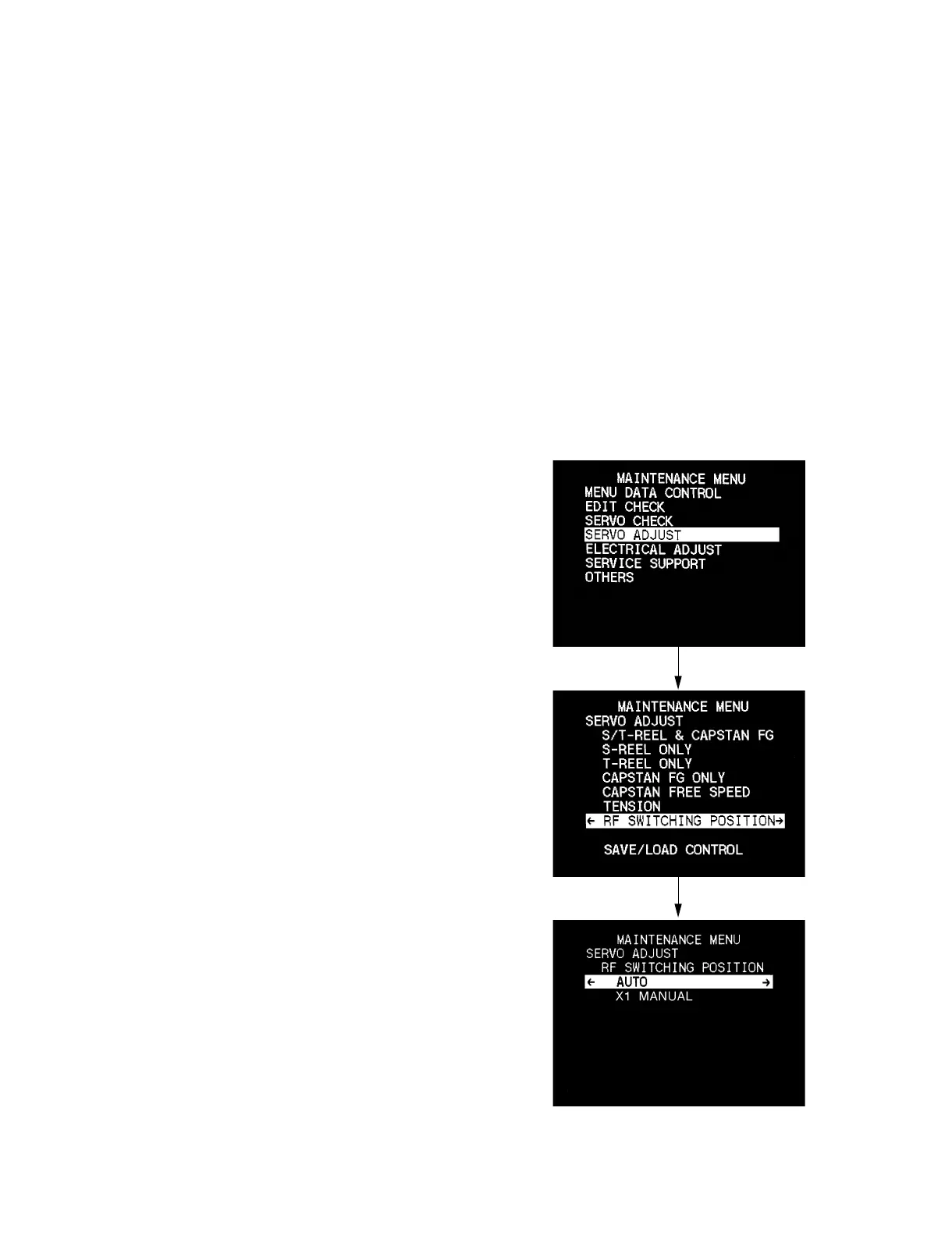
1. Show the maintenance menu on the monitor screen.
(1) While pressing the [&] key on the sub control panel, press
the [MENU] key to show the maintenance menu.
2. Press the [(], [)] keys and select “SERVO ADJUST”.
3. Press the [*] key to show the display 1.
4. Press the [(], [)] keys and select “RF SWITCHING
POSITION”.
5. Press the [*] key to show the display 2.
6. Press the [(], [)] keys and select “AUTO”.
. If you cannot proceed to the next step, perform the
MANUAL adjustment.
1
2


 To Next Page