21
HCD-VX888
Note: Clear RF signal waveform means that the shape “◊” can be
clearly distinguished at the center of the waveform.
RF signal waveform
E-F Balance (1 Track jump) Check
Procedure:
1. Connect an oscilloscope to TP (TEO) and TP (DVC).
2. Turned Power switch on.
3. Load a disc (YEDS-18) and playback the number five track.
4. Press the u button. (Becomes the 1track jump mode.)
5. Confirm that the level B and A (DC voltage) on the oscilloscope
waveform.
1 track jump waveform
Specification level: x 100=less than ±22%
6. After check, remove the lead wire connected in step 1.
RF PLL Free-run Frequency
Procedure :
1. Connect frequency counter to test point (XPCK) with lead wire.
2. Turned Power switch on.
3. Put the disc (YEDS-18) in to play the number five track.
Confirm that reading on frequency counter is 4.3218MHz.
oscilloscope
BD board
TP (TEO)
TP (DVC)
+
–
A
B
+
–
frequency counte
BD board
TP (XPCK)
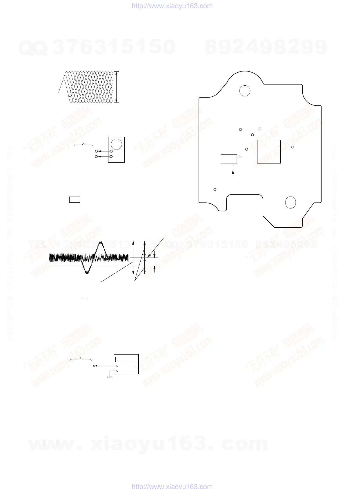
Adjustment Location :
[ BD BOARD ] — SIDE B —
IC103
IC101
TP
(RFDC)
TP
(FEO)
TP (TEO)
TP
(DVC)
TP
(RFAC)
17
TP
(VC)
TP
(XPCK)
TP
(FEI)
VOLT/DIV : 200mV
TIME/DIV : 500ns
level : 1.1 ± 0.3Vp-p
0V
Center of
waveform
B
Symmetry
A (DC voltage
level=1.3 ±0.6Vp-p
w
w
w
.
x
i
a
o
y
u
1
6
3
.
c
o
m
Q
Q
3
7
6
3
1
5
1
5
0
9
9
2
8
9
4
2
9
8
T
E
L
1
3
9
4
2
2
9
6
5
1
3
9
9
2
8
9
4
2
9
8
0
5
1
5
1
3
6
7
3
Q
Q
TEL 13942296513 QQ 376315150 892498299
TEL 13942296513 QQ 376315150 892498299
http://www.xiaoyu163.com
http://www.xiaoyu163.com

 Loading...