166
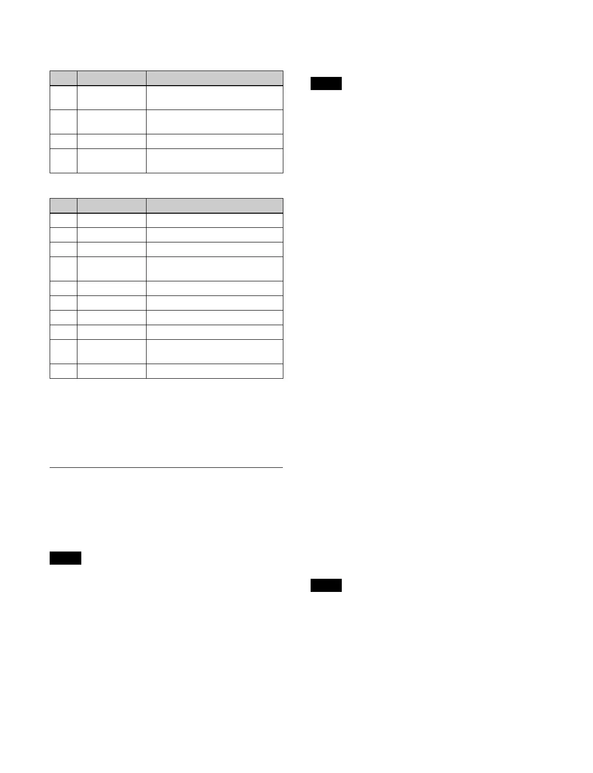
Frame I/O (2-channel mode) pattern numbers
2861 to 2864
Brick (3-channel mode) pattern number 3601
a) The [Height] parameter in numbers 1-3 and 2-3 are common.
b) Side V/side H image horizontal center position. At –100.00, the center is
at
the left edge of the screen. At +100.00, the center is at the right edge
of the screen.
c) Side V/side H image vertical center position. At –100.00, the center is at
t
he bottom edge of the screen. At +100.00, the center is at the top edge of
the screen.
Setting Modifiers
You can add modifiers to modify a DME wipe pattern.
Direction
Sets the direction of travel of the DME wipe.
• The direction cannot be set for the following patterns.
- Frame I/O pattern numbers 1201, 1202, 1203, 1205,
1
206, 1208, 1209, 1225
- P in P pattern number 1251
- Mosaic pattern number 1701
- Defocus pattern number 1702
• In a key DME wipe, the direction can be set for the
fo
llowing patterns.
- Frame I/O pattern numbers 1204, 1207, 1221 to 1224
- Resizer Frame I/O pattern numbers 7204, 7207, 7221
t
o 7224
Edge
Adds a border to a DME wipe pattern.
The edges cannot be set for the following patterns.
• Split pattern numbers 1011, 1012, 1013
• Mosaic pattern number 1701
• Defocus pattern number 1702
Position
You can move a DME wipe pattern to a desired position.
You can move to a specified position (upper left, upper
r
ight, bottom left, bottom right) using Position Select.
The position can be set for the following patterns.
The target position and movement varies depending on
t
he pattern.
• Squeeze pattern number 1031
Resizer Squeeze pattern number 7031
As the transition progresses, the pattern center
a
utomatically moves from the initial set position toward
the center of the screen.
• Squeeze pattern numbers 1032, 1033
You can set the pattern position at the start of the
t
ransition. As the transition progress resumes after the
dead band, the pattern automatically moves from the
initial position toward the center of the screen.
• Frame I/O pattern numbers 1201 to 1209, 1221 to 1225
P in P pattern number 1251
Resizer Frame I/O pattern numbers 7201 to 7208, 7221
to
7224
You can set the pattern position at the end of the first
t
ransition.
• P in P pattern numbers 2651, 2652
You can configure each channel separately, or
conf
igure two channels simultaneously, depending on
their relative positions.
• Brick pattern numbers 2801 to 2804, 2811 to 2814
You can set the vertical position where the brick slides
in
.
• Frame I/O pattern numbers 2851 to 2854, 2861 to 2864
You can set the pattern position at the end of the first
t
ransition for each channel.
Size
Sets the size of a DME wipe pattern.
The size can be set for the following patterns.
• Frame I/O pattern numbers 1201 to 1209, 1221 to 1225,
285
1 to 2854, 2861 to 2864
• P in P pattern numbers 1251, 2651, 2652
• Resizer Frame I/O pattern numbers 7201 to 7208, 7221
to
7224
Crop
Crops the top, bottom, left, right sides of a DME wipe
pat
tern.
No. Parameter Adjustment
1 Rot X Rotation around Y-axis (rotation in
ho
rizontal direction)
2 Rot Y Rotation around X-axis (rotation
in
vertical direction)
3 Rot Z Rotation around Z-axis
5 Delay Timing for image selected on a
u
tility bus to enter the frame
No. Parameter Adjustment
1-1 Side V Size X Side V horizontal scaling factor
1-2 Side V Size Y Side V vertical scaling factor
1-3 Height Height of brick
a)
1-4 Side V Center X Side V horizontal center position
b)
1-5 Side V Center Y Side V vertical center position
c)
2-1 Side H Size X Side H horizontal scaling factor
2-2 Side H Size Y Side H vertical scaling factor
2-3 Height Height of brick
a)
2-4 Side H Center X Side H horizontal center position
b)
2-5 Side H Center Y Side H vertical center position
c)
Notes
Note
Note
 Loading...


