64
Side view
a U (signal ground) terminal
Connect to a ground wire.
ICP-X1000 Series Control Panel
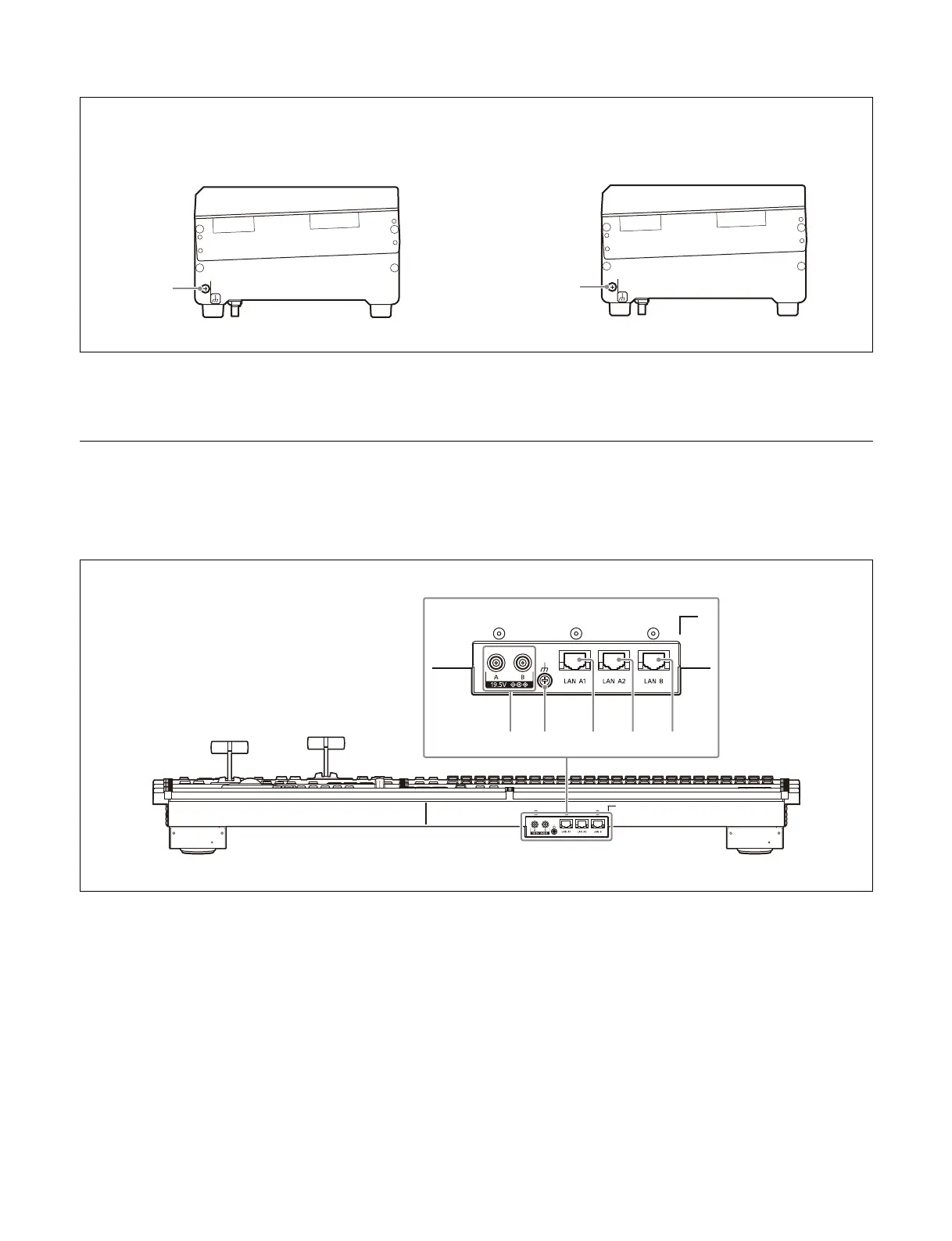
Rear view
The following illustration shows the ICP-X1224.
a DC IN A an
d B connectors
Connect to the supplied AC adaptor.
b U (si
gnal ground) terminal
Connect to a ground wire.
c L
AN A1 connector (RJ-45, 1000BASE-T
compliant)
Connect to the switcher system network via an Ethernet
swit
ch.
Connect to the switcher in system configurations that do
no
t use an Ethernet switch.
d L
AN A2 connector (RJ-45, 1000BASE-T
compliant)
Connect to a computer for menu operations in system
conf
igurations that do not use an Ethernet switch.
e L
AN B connector (RJ-45, 1000BASE-T
compliant)
Used for LAN A1 connector redundancy.
a
ICP-X7000 Integrated Control Panel MKS-X7075 Extension Adaptor
 Loading...


