88
a) Selects the utility 2 bus on the sub side when in multi program 2 mode.
Selecting Signals
Assigning Signals
Signals input to the input connectors and signals
generated within the switcher can be selected using the
cross-point buttons.
Each button number has assigned to it a video signal and
a key
signal, forming a pair.
For details, see “Creating a Cross-Point Assign Table”
(page 383).
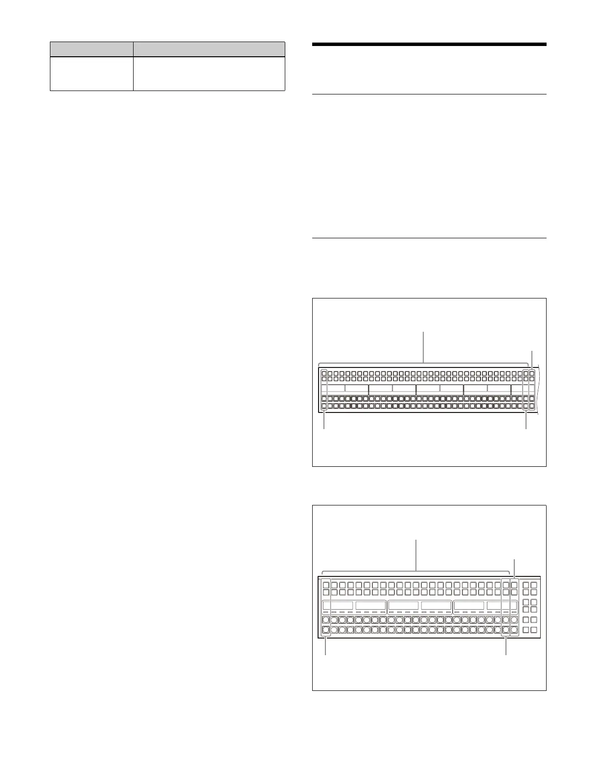
Cross-Point Button Numbers
ICP-X7000 36-button cross-point control block/
AUX bus control block
ICP-X1000 series 24-button cross-point control
bl
ock
DME1 key bus to
DME4 key bus
Press the [DME1K] to [DME4K]
buttons in the 1st row/2nd row,
turning them on.
Bus Assignment operation
1 to 35 (1st button number: unshifted state)
36 to 70 (2nd button number: shifted state)
SHIFT button
Number 1 (unshifted)
Number 36 (shifted)
Number 35 (unshifted)
Number 70 (shifted)
1 to 23 (1st button number: unshifted state)
24 to 46 (2nd button number: shifted state)
SHIFT button
Number 1 (unshifted)
Number 24 (shifted)
Number 23 (unshifted)
Number 46 (shifted)
 Loading...


