20
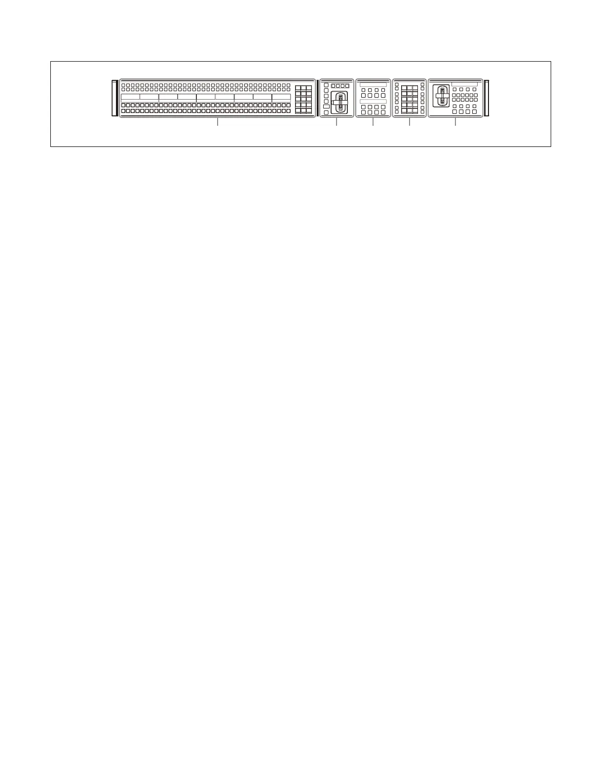
Configuration example using a simple-type transition control block
a AUX b
us control block (see page 42)
A cross-point module connected in an AUX bank row is
used
as an AUX bus control block.
The number of cross-point buttons varies depending on
t
he module. The MKS-X7017 has 36, the MKS-X7018
has 28, and the MKS-X7019 has 20.
b AUX b
ank
Up to two AUX bank rows (AUX 1, AUX 2) can be
con
figured.
For details, see “Assigning a Switcher Bank/AUX”
(page 400).
c M
/E banks (switcher banks)
You can assign switcher banks (M/E-1 to M/E-5, P/P) to
up
to six M/E bank rows.
For details, see “Assigning a Switcher Bank/AUX”
(page 400).
d C
ross-point control block (see page 21)
A cross-point module connected in an M/E bank row is
used
as a cross-point control block.
The number of cross-point buttons varies depending on
t
he module. The MKS-X7017 has 36, the MKS-X7018
has 28, and the MKS-X7019 has 20.
e T
ransition control block (see page 25)
Transition control block modules are enabled only when
con
nected in an M/E bank row.
f F
lexi Pad control block (see page 30)
Flexi Pad control block modules are enabled only when
con
nected in an M/E bank row.
g Num
eric keypad control block (see page 39)
Up to one numeric keypad control block module can be
con
nected.
h Ut
ility/shotbox control block (see page 41)
Up to two utility/shotbox control block modules can be
con
nected.
i Dev
ice control block (see page 35)
Up to one device control block module can be connected.
j Key c
ontrol block (see page 31)
Up to four key control block modules can be connected.
k T
ransition control block (simple type) (see
page 27)
Transition control block (simple type) modules are
enabl
ed only when connected in an M/E bank row.
l I
ndependent key transition control block (see
page 29)
Independent key transition control block modules are
enabl
ed only when connected in an M/E bank row.
m Key fa
der control block (see page 33)
Up to four key fader control block modules can be
conn
ected.
 Loading...


