– 30 –
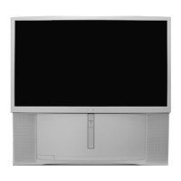
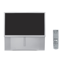
KP-44PS2/44PS2U/51PS2
RM-903
SECTION 5
SAFETY RELATED ADJUSTMENT
When replacing the following components marked with ] on
the schematic diagram, always check hold-down voltage and
if necessary re-adjust.
5-1. HV HOLD-DOWN ADJUSTMENT
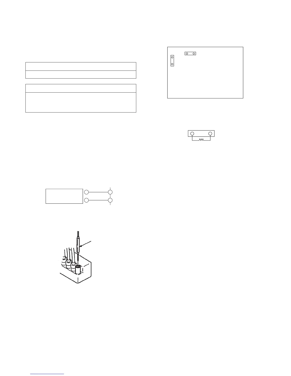
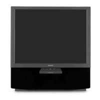
1. Connect HV static voltmeter to HV Block.
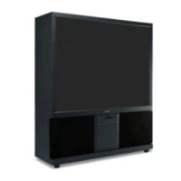
2. Mount a resistor (R9901 : 43 k , 1/4 W, METAL
FILM) at CN5003.
3. Remove CN5002 and connect External Power Supply to
CN5002 1 pin (+135 V) and 2 pin (GND).
4. Turn on the set.
Part Replaced (])
D Board C5123, C5127, C5130, C5143, D5115,
D5204, Q5104, R5136, R5138, R5140,
R9901, T5102, T5104, T5103 (FBT)
Part Replaced ([)
R9901
5. Receive the Dot signal and set PICTURE/BRIGHTNESS
to minimum.
6. Slowly up the supply voltage from 0 V to 135 V until
hold-down circuit works (picture disappear).
7. Read the HV static voltmeter of peak HV voltage.
Spec : 33.7 ~ 35.3 kV
8. If Hold-down voltage is less than 33.7 kV then replace
R9901 of 43 k with that of 39 k , and check if the
voltage is within the spec.
9. If hold-down voltage is over than 35.3 kV then replace
R9901 of 43 k with that of 47 k , and check if the volt-
age is within the spec.
+
–
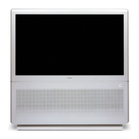
1
CN5002
Power
Supply
2
D BOARD
– CONDUCTOR SIDE –
CN5002
CN5003
CN5003
R9901
Fig. 5-1
Fig. 5-2
Fig. 5-3
Fig. 5-4
Remove the cap off
from the unused
terminal and connect a
HV static voltmeter
there.