English
4 (E)
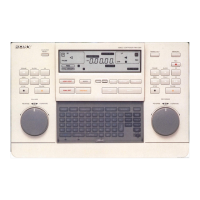
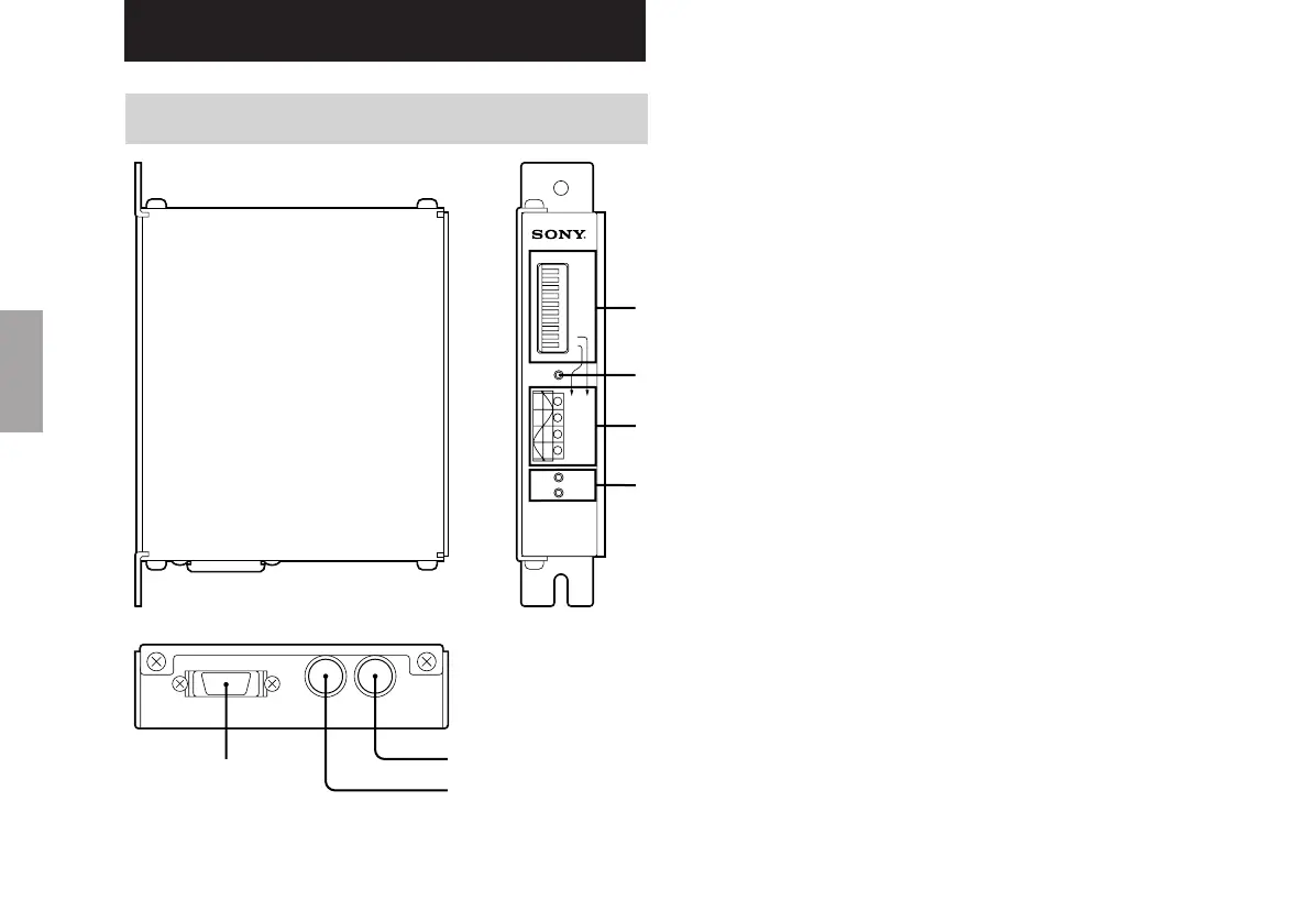
1 MODE switch
3 POS. lamp
4 ALARM lamp
7 Head cable connector
6 Reference point connector
ALM
LEVEL
SPEED
MJ100
OFF OFF
ON OFF
OFF ON
ON ON
ABS
1
12345678910
2
3
4
5
6
7
8
9
10
MODE
OFFON
Fig. 3-1
5 Output connector
3. Operation
3-1. Name of each part
2 ABS lamp
1 Mode switch
Sets the reference point, A/B phase
direction, and resolution.
2 ABS lamp
Lights when the reference point input signal
is ON.
3 POS. lamp
Used while setting the reference point.
4 ALARM lamp
Lights when an alarm is generated. LEVEL
indicates a level alarm for the input signal,
while SPEED indicates an excess speed
alarm.
5 Output connector
This connector is used to input power and to
output each signal.
6 Reference point connector
Connector used for reference point signal
input.
7 Head cable connector
Connector for head unit signal input.