English
6 (E)
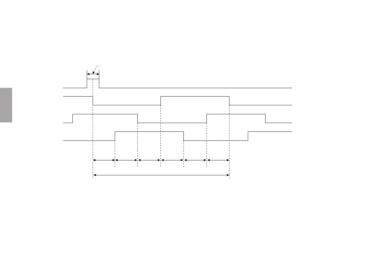
The MJ100 outputs U/V/W phase as shown in Fig. 3-3.
Fig. 3-3
P1 P2 P3 P4 P5 P6
λ
TM (1 cycle of A phase when reference point output is in Z mode)
Z
U phase
V phase
W phase
Phase between each edge
P1 to P6
. These output waveforms are for when a 360d electrical angle is taken for λ (PL25: 5 mm; PL60: 2 mm).
. U phase falls at the center of the Z pulse (one A phase cycle in width). U phase is synchronized with the A phase of A/B.
. P1 through P6 give the phase relationships between each edge. P = 60d ±3.6d
. During alarm output, the U/V/W phase do not become high impedance.





 To Next Page