Installation
6 (GB) Installation
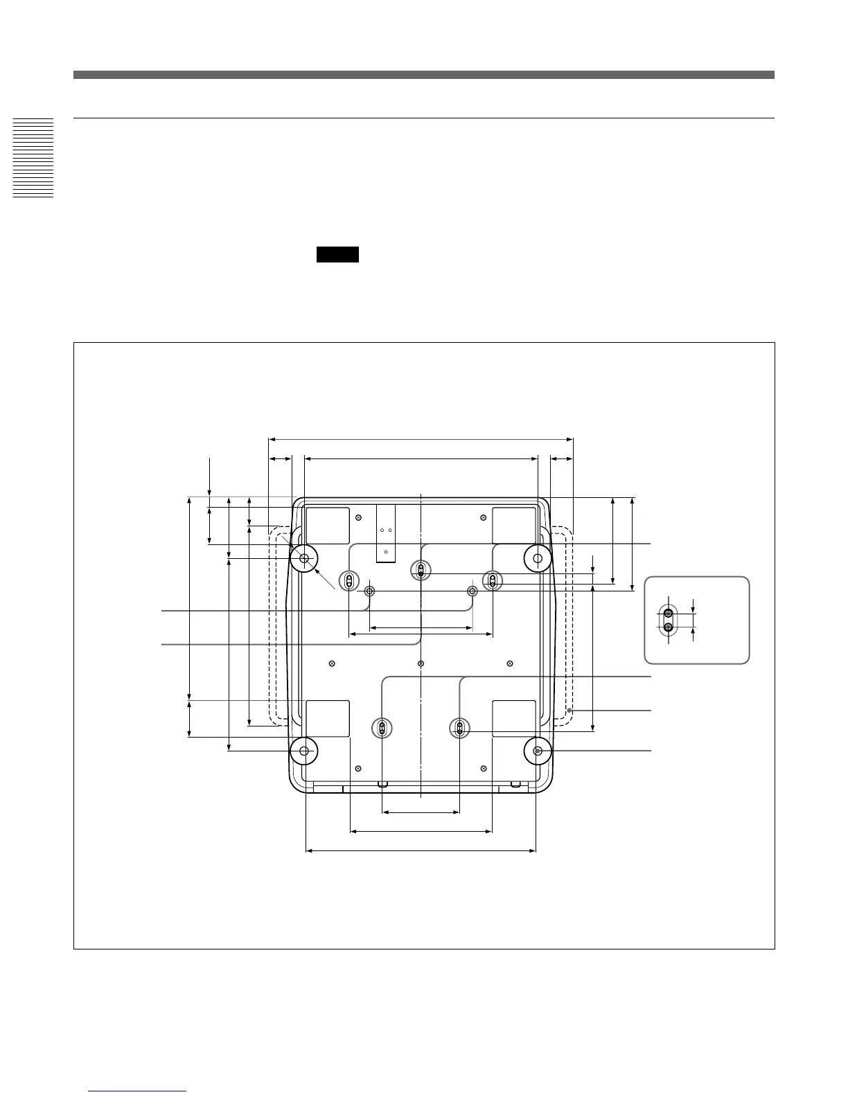
Bottom
The standard hole for installation on the bottom surface is useful for
reference when measuring for installation. There are seven holes on the
bottom surface of the projector. For ceiling installation using the optional
PSS-70 Projector Suspension Support, use five holes to attach the PSS-70.
The other two holes are spare ones.
Notes
• Use only the M8 meter screws of 10 mm (
13
/
32
inches) to 30 mm (1
3
/
16
inches)
long for the attachment holes for the PSS-70.
• When attaching the PSS-70, use the M8 meter screws of 20 mm (
25
/
32
inches)
supplied with the PSS-70.
Installation Diagrams
Unit: mm (inches)
524 (20
5
/8)
322 (12
11
/16)
679 (26
23
/32)
22.8 (
29
/
32
)
137.8 (5
7
/
16
)
83 (3
9
/
32
)
64.8 (2
9
/
16
)
451 (17
3
/
4
)
435 (17
1
/
8
)
457.8 (18
1
/
32
)
83 (3
9
/
32
)
230 (9
1
/
16
)
174 (6
27
/32)
318 (12
17
/32)
515 (20
9
/32)
330.7 (13
1
/
32
)
194.6
(7
21
/
32
)
211.8 (8
11
/
32
)
25 (
31
/
32
)
14 (
9
/
16
)
Holes for attaching
the PSS-70/spare
holes (M8 meter
screws, 20 mm
(
25
/32 inches))
Holes for attaching the
PSS-70/Spare holes
Receptacles for
the projections
of the PSS-70
Standard hole
for installation
Handle
Adjuster
Ø 60
Holes for attaching
the PSS-70
Spare holes
50 (1
31
/32)
50 (1
31
/32)