Installation
Installation 15 (GB)
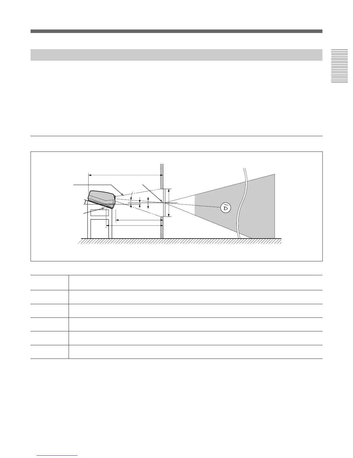
Floor Installation Using Rear Projection Flat Screen
What is the optical axis angle?
The optical axis angle is the angle between the horizontal level line and the
straight line from the center of the projector’s green lens to the center of
the screen. When using a rear projection screen, you can get the brightest
picture when the center of the screen is aligned with a straight line
extension of the center of the green lens.
Therefore, the most suitable optical axis angle varies depending on the
height of the screen and your line of sight.
When the optical axis angle is 2°
Unit: mm (inches)
60 70 80 90 100 120 150 180 200 250
A (Vsize) 914 1067 1219 1372 1524 1829 2286 2743 3048 3810
(36) (42) (48) (54) (60) (72) (90) (108) (120) (150)
B (Hcent) 140 130 120 110 100 80 49 18 -3 -54
(5
5
/8) (5
1
/4) (4
3
/4) (4
3
/8) (4) (3
1
/4) (1
15
/16)(
23
/32)(-
1
/8) (-2
1
/8)
E (Xlens) 1977 2265 2556 2846 3136 3712 4599 5482 6075 7544
(77
7
/8) (89
1
/4) (100
3
/4) (112
1
/8) (123
1
/2) (146
1
/4) (181
1
/8) (215
7
/8) (239
1
/4) (297
1
/8)
F (Lhole) 2172 2460 2751 3041 3331 3907 4794 5677 6270 7739
(85
5
/8) (96
7
/8) (108
3
/8) (119
3
/4) (131
1
/8) (153
7
/8) (188
3
/4) (223
5
/8) (246
7
/8) (304
3
/4)
G (Lmax) 2655 2943 3234 3524 3814 4390 5277 6160 6753 8222
(104
5
/8) (115
7
/8) (127
3
/8) (138
3
/4) (150
1
/4) (172
7
/8) (207
7
/8) (242
5
/8) (265
7
/8) (323
3
/4)
Necessary parts modifications
Changing the polarity used for “Floor installation, rear projection”
For details, see “Changing the Polarity” on page 20 (GB).
B
0
+
–
Center of the screen
Optical axis
angle
15.5°
Standard hole for
installation
Floor
E
F
2°
A
Wall
G
Screen size
(inches)
Screen with 4:3 aspect ratio