25/08/2004 ©
Söring
Service-Manual Arco- and RF-units
1
not valid for A-3000/ -2000
2
not valid for Arco-2000
-19-
3
not valid for MBC600
4
not valid for Arco-1000
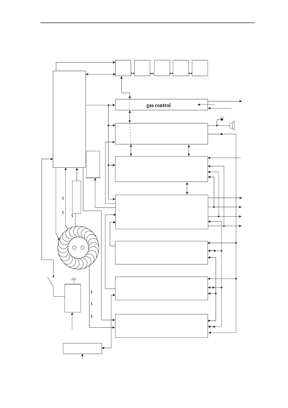
Block diagram of units
IC
2
IC
2
IC
2
CPU
Handpiece recognition
HSE
RF-Out-Module
PE
Bipolar
Act2
Act1
PE
Bipolar
HS2
HS1
Cut module
(Sinus)
Coagulation module
(Pulse)
High power supply 0-100V
+/- 15V
control-/display unit
(Frontpanel)
mains board
-low power supply
-smoothing
-voltage selector switch
-Softstart-relays
-Microprocessormonitoring
-clear switching of power
-Relays
-Output transformers mono/bipo
-power detection
-PE monitoring
-Bipolarautomatic
Test
resistor
IC
2
supply (5)
5V / +/-15V
5V
CPU-
monitoring
(6)
(2)
(2)
(6)
(14)
(20)
(8)
(2)
(2)
(1)
(1)
(8)
(8)
(6)
Synchro
mains filter
rectifier
Modulestatus B (8)
Modulecontrolbus B (14)
supply B (5)
RF (2)
RF (2)
150=/Softstart (4)
mains
mains switch
primary (4)
Statusbus (14)
16V 18V 18V (6)
21V 18V
110V
(2)
(2)
(14)
Numbers in square brackets are plug contacts !!!
Numbers in round brackets are polarities of cables !!!
MA_PM
[J8]
[J5]
[J5]
[J2]
[J2]
[J1]
[J5]
[J3]
[J7]
[J7]
[J4]
[J2]
[J6]
[J4]
[J14]
[J4]
*[J1]
[J8]
*[J4]
[J2]
[J1]
[J1]
*[J1]
*[J1]
*[J3]
*[J3]
[J2]
[J2]
[J1]
[J7]
[IC-Sockel]
[J1]
Synchro signal
[J3]
[J4]
[J5]
[J2]
[J3]
[J5]
*[J3]
[J6]
[J13]
[J16]
[J1]
[J2]
[J3]
[J8/J9]
[J5]
[J7]
[J6]
[J7] [J1]
[J2]
[J1]
(2)
[J7]
(14)
(14)
[J1] [J1] [J1] [J1] [J1]
[J1] [J1] [J1] [J1]
BI_PM
MG_PM
MG_PM
MG_PM
(8)
(8) (8)
(8)
valves (6)
sensors (6)
Gassensor (2)
footswitch (8)
Handpiecebus
*on piggy-
backboard
*on Interface
*on Interface
(2)
[J1]
[J8][J9]
(4)
Poti