25/08/2004 ©
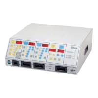
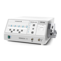
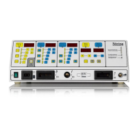
Söring
Service-Manual Arco- and RF-units
1
not valid for A-3000/ -2000
2
not valid for Arco-2000
-58-
3
not valid for MBC600
4
not valid for Arco-1000
12.2. Error indication at system start
On start of the system a self-test is performed, which checks various power supply
parameters for correct function. If an error is detected, the error code is shown in the
very left 7-segment display. The indication is divided into the function group (e.g.:1) and
the function (e.g.:2), divided by a decimal point. The exact explanation of the error codes
is given on pages 70pp.
12.3. Configuration of important bus cables and connectors
In the following table of pin configuration "top" refers to the opened bottom plate
(construction state of the equipment), sighting is from the front panel. For flat cables with
mica plugs the brown wire (with colored cables) respectively the red wire (with gray
cables) is pin 1. The counting of pins goes from top to bottom respectively from left to
right.
Bus cable / plug connects Pin description Remarks
High power supply
Plug J1
Transformer
1
18V~
2
3
18V~
4
5
16V~
6
18/18/ 16V~
(vertical, right)
Plug J2
Power supply board
1 Relay
2 Relay
3 +
150V=
4 -
Feeding high power
supply
Soft start relay
(vertical, right)
Supply bus
High power supply
Coag module
Cut module
1 +
0 - 100 V
2 Ø
3 +15 V
4 Ø
5 - 15 V
Supply modules
(vertical, right)
Mascon-plug
Module control bus
(MSB)
High power supply
Coag module
Cut module
CPU
1-12: Data
13: 0V
14: 5V
Control of power
modules
(left of Power supply)
(right other modules)
Module status bus
High power supply
Coag module
Cut module
RF-output module
Pin 1: 0V
Pin 2: U
Pin 3: I
Pin 4: 0V
Pin 5: DOWN
Pin 6-8: Status
transmission current /
voltage of power
supply
Report of module
status
(position as for MSB)
Coagulator module
Plug J7
RF-output module 1: RF
2: RF
left at module, to right
for RF-output module