25/08/2004 ©
Söring
Service-Manual Arco- and RF-units
1
not valid for A-3000/ -2000
2
not valid for Arco-2000
-3-
3
not valid for MBC600
4
not valid for Arco-1000
Contents
Page
1. Overview.........................................................................................................10
1.1 General description of the Arco-units, MBC-units ...................................................... 10
1.2 Co-operation of units........................................................................................................... 12
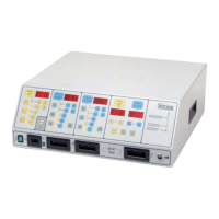
Arrangement of modules of the Arco-3000 .................................................13
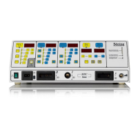
Arrangement of modules of the Arco-2000 .................................................14
Arrangement of modules of the Arco-1000 .................................................15
Arrangement of modules of the Arco-1000 Table-Top..............................16
Arrangement of modules of the MBC 601....................................................17
Arrangement of modules of the MBC 600....................................................18
Block diagram of units.....................................................................................19
Block diagram primary current supply of the units ..................................20
Description of units..........................................................................................21
2. Primary power supply..................................................................................21
2.1 Description of power supply board ................................................................................. 21
Block diagram mains board 1/2 .....................................................................23
Block diagram mains 2/2.................................................................................24
3. Description of microcontroller unit, board CPU....................................25
3.1. General description ............................................................................................................ 25
3.2. Connection to other units ................................................................................................. 25
3.2.1. Connection to frontpanel................................................................................................... 25
3.2.2. Connection to handpiece recognition unit...................................................................... 25
3.2.3. Connection to high-power supply.................................................................................... 25
3.2.4. Connection to Cut-module
4
............................................................................................... 25
3.2.5. Connection to Coag-module............................................................................................. 25
3.2.6. Connection to relay board ................................................................................................ 25
3.2.7. Connection to the mains relay board.............................................................................. 26
Block diagram CPU board...............................................................................27
4. Description of front panel...............................................................................28