25/08/2004 ©
Söring
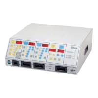
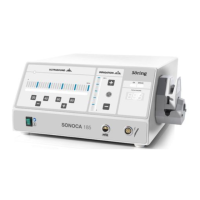
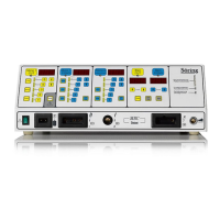
Service-Manual Arco- and RF-units
1
not valid for A-3000/ -2000
2
not valid for Arco-2000
-85-
3
not valid for MBC600
4
not valid for Arco-1000
14. Technical checks regarding safety (TSC)
The safety concept comprises
- patient protection
-- Patient electrode contact recognition
-- Check of pre-selected parameters (output power error)
-- Automatic self test on start of equipment
-- Technical checks regarding safety
Furthermore the Cut-module and the Coag-module are short-term short-circuit proof. The
high-power supply is equipped with an over-current disconnection and is permanently
short-circuit proof. A check of power supply (correct voltage), of the switch-on stage
within the Cut- and Coag-module (no current drain with applied supply voltage) as well as
a test of indicators is performed at every switch-on of the equipment. A watch-dog
prevents uncontrolled conditions in case the software fails.
14.1. Intervals
Safety-technical checks have to be carried out annually.
14.2. Extent
Check for presence of equipment book and instruction-manual.
- Check for electrical safety according to DIN VDE 0751m- part 1: 1989
- Check of protective conductor (<0.3
Ω
)
- Check of equipment leakage current (case) (< 0.5 ma)
- Patient leakage current monopolar application part (<10µA)
- Patient leakage current bipolar application part (< 10µA)
- Check of controls and indicators
- Check of RF-generators (delivery of power)
- Check of RF-leakage current (handpieces, PE-electrode)
- Check of patient electrode monitoring
- Check of power monitoring
- Check of handpieces and foot switches for proper condition
14.3. Description of special checks
14.3.1 Check of controls and indicators
- Connect handpieces and patient electrode according to instruction manual
- Switch-on equipment and check indicator-lights
- Select a power-step for cutting
4
and coagulation
4
and activate
handpiece switch (blue or yellow button respectively footswitch)
Acoustical signal for cutting and coagulation must be
present
Handpiece-mode recognition must light up
- Connect bipolar connecting cable
2,4
and bipolar tool according to
instruction manual. Bipolar-mode recognition must light up. If necessary
press a key within the bipolar field and activate foot switch
- Acoustical signal for bipolar function must be present
- Bipolar-mode recognition must light up