Applying ViSi Mobile Monitoring System / Initiate
71
5 lead-wire and ECG Electrode Placement
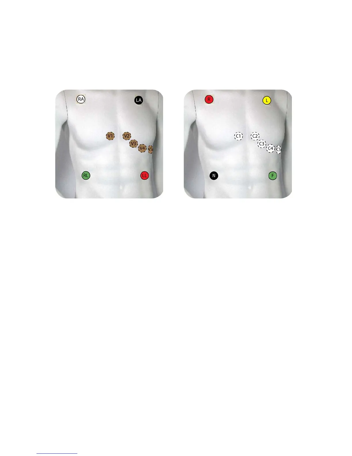
With the 5 lead-wire Chest Sensor, the ECG channel is capable of monitoring seven leads simultaneously
(Lead I, II, III, aVR, aVL, aVF, and a V lead). The ability to monitor multiple leads simultaneously
improves beat detection to determine the HR and minimizes false detections as a result of artifact. The
ECG electrode placement shown in the diagram below is recommended.
Note: Place the V lead in the position appropriate to your monitoring requirements: V1, V2, V3,
V4, V5 or V6.
Note: The ECG waveform can be displayed one lead at a time on the ViSi Mobile Monitor.
V1/C1 4th intercostal space (just right of sternum)
V2/C2 4th intercostal space (just left of sternum)
V3/C3 Midway between V2 and V4
V4/C4 Mid clavicular line, 5th intercostal space
V5/C5 Anterior axillary line, in line with V4, or 5th intercostal space
V6/C6 Mid axillary line, in line with V5, or 5th intercostal space
lead-wire Color Code - U.S. (AAMI)
RA - White
LA - Black
LL - Red
lead-wire Color Code - International (IEC)
R - Red
L - Yellow
F - Green
V - Brown
RL - Green
C - White
N - Black



 To Next Page