INSTRUCTION MANUAL
SPACE s.r.l.
ER 200 - ER 220
ER150 - ER160 - ER165
Code M0076 - rev.1.6
(04/2005)
Page 26/ 40 SPACE s.r.l. – 10090 Trana (TO) Via Sangano, 48
Tel. (+39) 011/ 933.88.65 – Fax (+39) 011/ 933.88.64
e-mail: info@spacetest.com
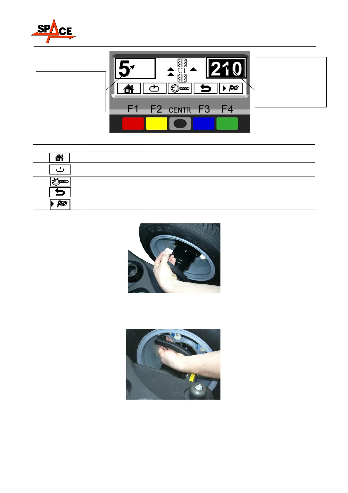
Figure 28
ICON KEY DESCRIPTION
RED (F1) Return to initial program phase
YELLOW (F2)
Displays next row of keys
(MATCHING Procedure, mod.ER220/ER160/ER165 only)
CENTRE Displays the exact unbalance (pitch 1g instead of 5g)
BLUE (F3) Displays the previous page
GREEN (F4) In models ER220/ER160/ER165 performs spin
Fit the adhesive weight in the measurement rod as shown in Figure 29.
Figure 29
Read the external distance measurement on the measurement rod. Fit the adhesive weight on
the outside of the wheel (Figure 30) at the distance indicated (in the example at 210 mm)
using a known weight value. The position of the external weight is not visible but hidden
inside (para. 7.3.2 on page 21)
Figure 30
Read the internal distance measurement on the measurement rod. Fit the adhesive weight on
the inside of the wheel (Figure 30) at the distance indicated using a known weight value (in
the example 5g). Turn the wheel until the correct point is reached (para. 7.3.2 on page 21)
Check the wheel balance conditions by making a trial spin. The display screen will display an
unbalance reset. The ALU-S procedure is now completed.
Distance on black
background for
correcting the outside
unbalance.
Value displayed when
near to fitting point
Amount of weight to be
fitted to inside of
wheel.
Value displayed when
far from fitting point