INSTRUCTION MANUAL
SPACE s.r.l.
ER 200 - ER 220
ER150 - ER160 - ER165
Code M0076 - rev.1.6
(04/2005)
Page 14/ 40 SPACE s.r.l. – 10090 Trana (TO) Via Sangano, 48
Tel. (+39) 011/ 933.88.65 – Fax (+39) 011/ 933.88.64
e-mail: info@spacetest.com
7 WHEEL BALANCING
7.1 Determination of wheel dimensions
7.1.1 Manual setting of wheel dimensions for dynamic balancing and ALU 1, 2, 3, 4
functions
SPACE wheel balancers feature a manual gauge and a graduated scale for determining wheel
dimensions (Figure 7 and Figure 8).
The rim distance dimension is always set with "mm" unit of measurement.
The width and diameter dimensions on the other hand can be set in "inches" or "mm". The
examples shown in this manual show measurements in "inches". To change the unit of
measurement from "inches" to "mm", see chap. 11 on page 34.
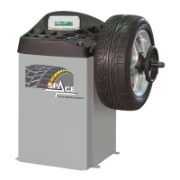
Figure 6
ICON KEY DESCRIPTION
RED (F1) Return to display previous page
YELLOW (F2) Decrease wheel dimension values
CENTRE Select and confirm the value to be set
BLUE (F3) Increase wheel dimension values
GREEN (F4) Perform spin
Press centre key ( ) to select the value to be set.
The display screen will show the selected value on black background and on the right the
same value in large characters (Figure 6).
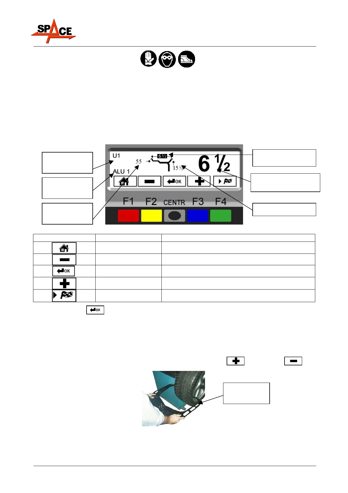
Manually set the width. Generally speaking, the nominal width is indicated on the rim, but it
is always a good idea to position the graduated scale on the inner and outer side of the wheel
as shown in Figure 7 and determine the measurement to be set.
To enter the wheel width, the operator must select the “PLUS”
or “MINUS” key
until the desired width is achieved.
Figure 7
Rim distance
value
Rim diameter
Selected dimension
displayed enlarged
User no. in use
Selected
program
Rim width (selected
im
n
i
n
MANUAL
GAUGE