MX800 Transceiver Technical Manual
© SPECTRA ENGINEERING 2006 Revision 4.2.3
102
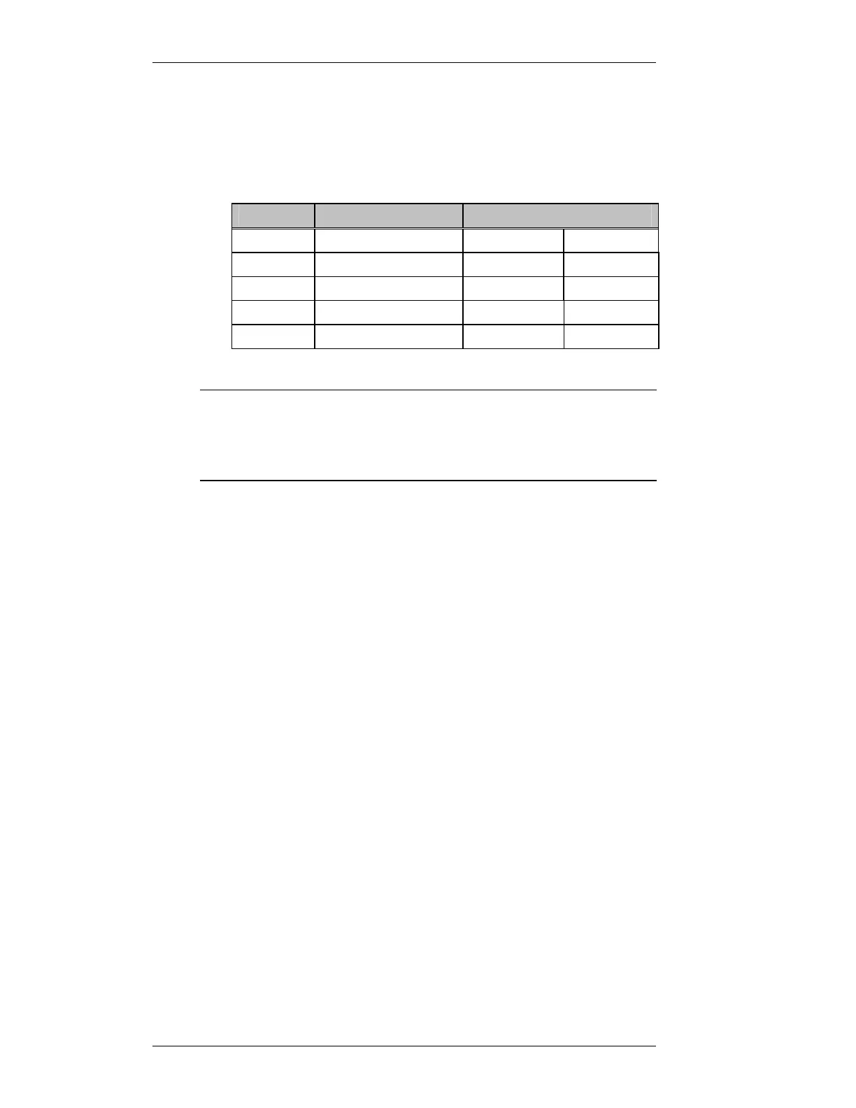
7.1.4 CN4 DB9 Male RS232 Connector
RS232 serial port to the MX800. It may be optionally located on the front
panel of the MX800. Only 3 wires are required for the MX800 TXD, RXD
and ground. The function of TXD and RXD pins can be interchanged by
changing jumpers JMP10 and JMP11. Table 7-5 below illustrates this.
Name
Function
JMP 10/11
(Referred to MX800) 2-3 1-2
CN4 Pin no CN4 pin no
TD Transmitted Data 3 2
RD Received Data 2 3
SG Signal Ground 5 5
Table 7-5 CN4 Connector Jumpers
Note
Both JMP10 and JMP11 must be set to the same positions. In
position 2-3 the radio will require a serial cable with the TXD and
RXD lines cross-connected. In position 1-2 a one to one cable is
required.
7.1.5 CN6 Simplex Relay/External Reference
This is an N type connector, which acts as the RF I/O port for simplex
operation. Optionally the RX input for duplex operation may use this port
instead of the BNC port or if an external reference is required this port can be
used.
7.1.6 CN7 RX Input
This is a BNC connector used as the RX RF input.
7.1.7 CN8 TX Output
This is an N type connector used as the TX RF power output.
7.1.8 CN9 RJ45
This connector may optionally be fitted. The function depends upon which
option board is fitted. A standard option is the isolated line I/O and this
connector is used for this function when this option is fitted. See Options
section for connection details.
A rectangular knock out section in the chassis provides for mounting of the
connector should it be required.