MX800 Transceiver Technical Manual
© SPECTRA ENGINEERING 2006 Revision 4.2.3
36
Refer circuit diagram CS022-1
3.10.2 Installation
Components Required:
1. Option board ‘MXOPT’ fitted for Power Save Mode. Qty-1
2. 16way female-to-female IDC Cable Assy. Qty-1
3. 3x20mm Standoff posts. Qty-4
Test Equipment Required:
1. Communications Test Set
2. MX800 Radio Interface Box
Method:
1. Remove the cover to the MX800 radio.
2. Remove the Motherboard from the MX800 radio.
3. Remove IC’s 21 and 27 from the Motherboard.
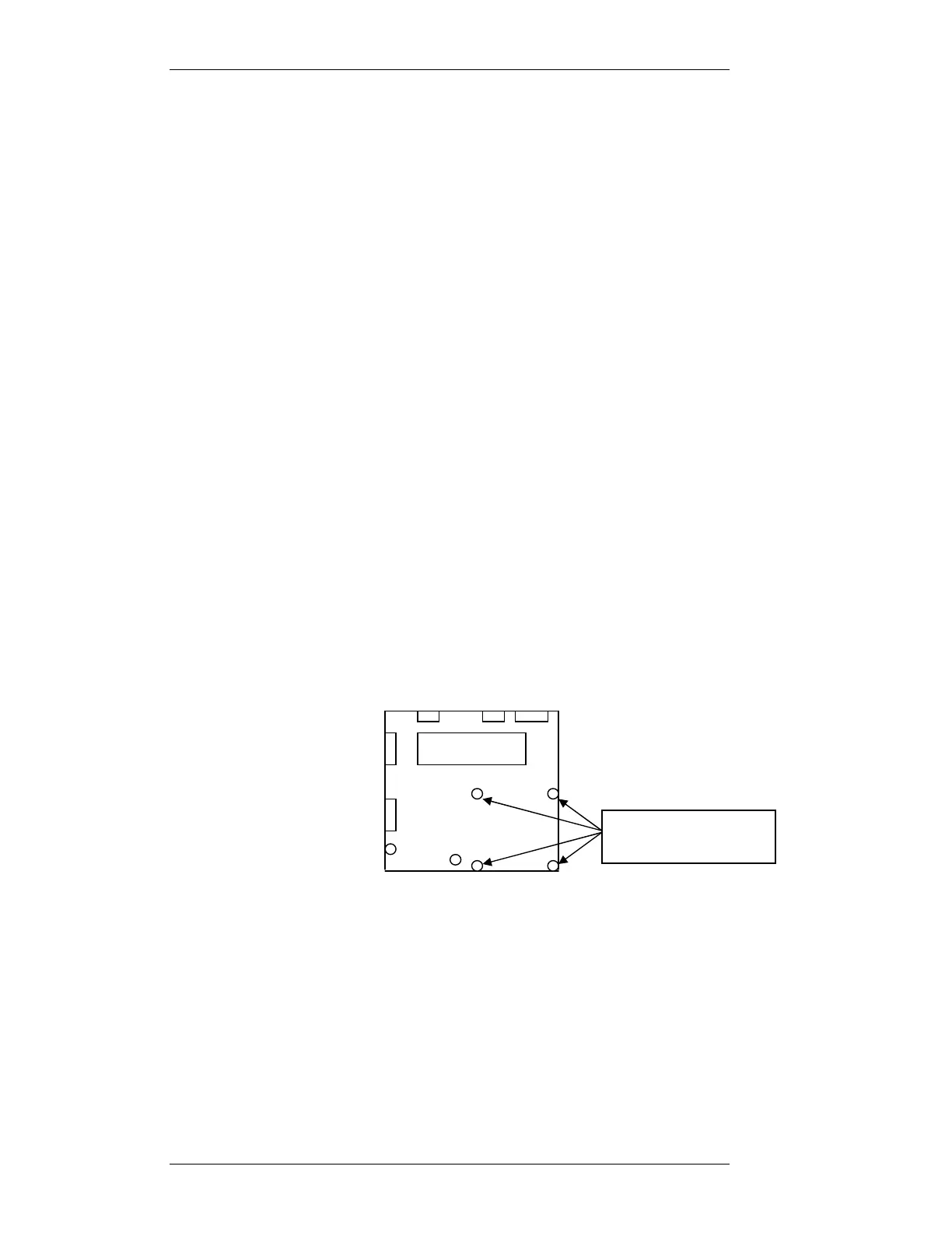
4. Reinstall the Motherboard into the MX800 radio and using the qty 4
3x20mm standoff posts in the positions indicated below:
5. Remove the Link jumpers off connector SKK.
6. Install the Option Printed Circuit Board onto the 4 standoffs with the
16way connector closest to DIP2 on the Motherboard. Secure with the
qty4 3x5mm machine screws previously removed.
7. Install the 16way-ribbon cable between connector SKK on the
Motherboard and SKK on the Option board, taking note that the cable is
correctly orientated.
Motherboard
3x5mm machine
screws to be removed