Technical Manual Alignment and Testing
© SPECTRA ENGINEERING 2006 Revision 4.2.3
79
Choose ‘OK’ to accept the changes made and then from the Channel Screen
choose ‘Send Data to MX800’. This then saves the changes that you have
made to the radio.
After balancing and setting the correct peak deviation is necessary to align
the reference oscillator and re-check the deviation alignment, as the reference
oscillator alignment affects the deviation. This may require running through
the deviation alignment again after the oscillator alignment procedure.
5.1.10 TX Centre Frequency Alignment
The reference oscillator alignment is used to set the correct centre frequency
for each channel. This can be done on a per channel basis or all channels can
be set at once. Oscillator alignment is done using a digital potentiometer
adjustment through the Channel Screen in MXTOOLS. To carry out this
procedure the transmitter output needs to be connected to a RF test set
displaying the frequency error. This procedure should be done after the
deviation alignment procedure has been done. Transmitter modulation should
be disabled.
To alter all channels at once use the ‘Lock Data’ option as described in the
power setup procedure. Alter the Reference Oscillator Frequency
potentiometer until the channel is “on frequency”. Choose ‘OK’ to accept the
changes made and then from the Channel Screen choose ‘Send Data to
MX800’. This then saves the changes that you have made to the radio.
To calibrate each channel individually make sure the ‘Lock Data’ option is
not selected and repeat the above procedure for each channel.
5.1.11 TX Line Input Level and Nominal Deviation
Alignment
There are three manual potentiometers associated with the TX deviation on
the motherboard. These are set by injecting the correct audio levels and
adjusting the potentiometers. The transmitter modulating audio is to be
connected to either the WB/DC-FM input or the TX VF input as described in
the procedures.
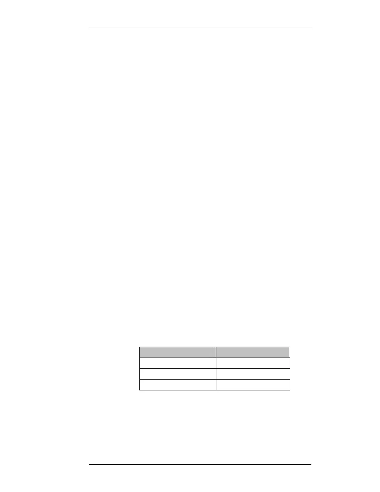
The required nominal deviation is dependent on whether the radio is narrow,
medium or wide. The following table lists the required level for each case:
Bandwidth
FM Deviation (kHz)
Narrow (12.5kHz spacing) 1.5
Medium (20kHz spacing) 2.4
Wide (25kHz spacing) 3.0
Table 5-2 Nominal Deviation
The first potentiometer RV2 sets the TX Limiter Gain. The transmitter
modulating audio for this test is connected to the WB/DC-FM input with