Technical Manual Alignment and Testing
© SPECTRA ENGINEERING 2006 Revision 4.2.3
77
Note
If the ‘Lock Data’ option is selected then any changes made to the
current channel are duplicated on all channels.
Select the ‘Continuous Update’ option on the Channel Edit Screen. This
allows real time updating of the potentiometer values to the radio. Thus any
changes made will be immediately reflected in the radio. Alter the Transmit
Power potentiometer until the power meter reads the required output power.
Choose ‘OK’ to accept the changes made and then from the Channel Screen
choose ‘Send Data to MX800’. This then saves the changes that you have
made to the radio.
To calibrate each channel individually make sure the ‘Lock Data’ option is
not selected and repeat the above procedure for each channel.
5.1.9 Peak Deviation and Modulation Balance
This procedure is used to set the peak deviation and modulation balance for
each channel. This can be done on a per channel basis or all channels can be
set at once. The alignment is done using the Channel Screen in MXTOOLS.
To carry out this procedure the demodulated output of the transmitter output
needs to be connected to a CRO or some other piece of equipment giving a
visual display of the demodulated output. IF Bandwidth of the RF test set
should be set at 20kHz or greater (230kHz on the HP 8920) and de-emphasise
should be off. The audio filters should be set at <20Hz HPF and 15kHz LPF.
To alter all channels at once use the ‘Lock Data’ option as described in the
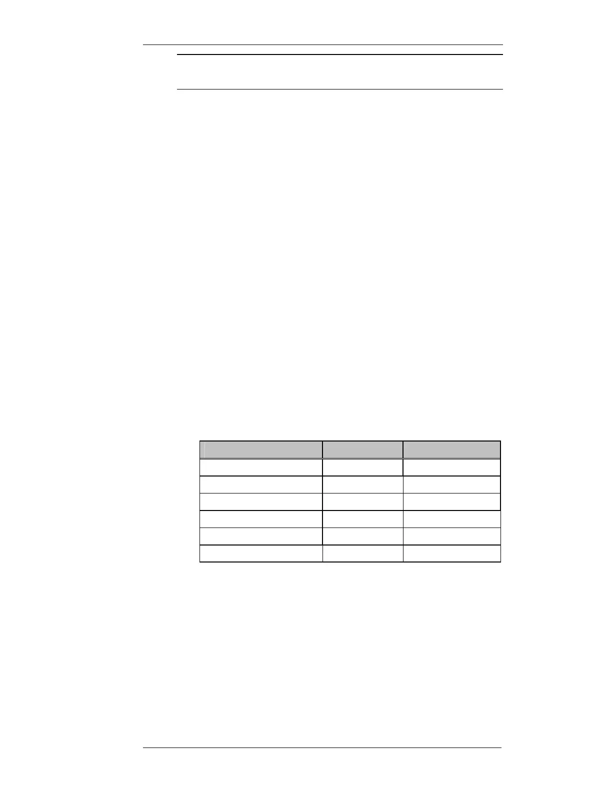
power setup procedure. The correct peak deviation is dependent on whether
the radio is narrow, medium or wide band and also whether the CTCSS
option is installed. The following table specifies the peak deviation in each
case.
Bandwidth
CTCSS Option
Peak Deviation (Hz)
Narrow (12.5kHz spacing) YES 2150
NO 2400
Medium (20kHz spacing) YES 3440
NO 3840
Wide (25kHz spacing) YES 4300
NO 4800
Table 5-1 Peak Deviation Settings
The setting of the peak deviation is done at 1kHz. The modulation balance is
done at 400Hz. The transmitter modulating audio for this test is connected to
the WB/DC-FM input with JMP8 set to 1-2. This input is located on the rear
of the MX800, on the Line I/O connector pin 13 of the DB15F connector.