MX800 Transceiver Technical Manual
© SPECTRA ENGINEERING 2006 Revision 4.2.3
6
1.1.1 Rear Panel
Figure 1-3 below and Table 1-2 Details the functions of each connector.
Connector #
Conn Type
Function
Description
CN5 3 PIN DC Power input 13.8 Volt DC power input. Also +28 Volt
input on spare pin if required.
CN6 N TYPE Simplex relay out or
N type RX input
Location for internal simplex relay. The
antenna for RX / TX connects to this point.
Alternatively an N-Type connector can be
used for the input to the receiver for full
duplex operation.
CN7 BNC RX input Standard BNC connector for the input to the
receiver for full duplex operation.
CN8 N TYPE TX output The RF power output from the transmitter for
full duplex operation.
CN9 RJ45 Spare Knockout provision for RJ45 connector.
CN3 DB25-F Parallel I/O Provides one 8 bit input port. One parallel 8
bit BCD or Binary channel select input and
one 8-bit output port.
CN1 DB15-F Line I/O Provides the necessary analog receiver and
transmitter interface for system interfacing.
CN4 DB9-M RS-232 serial port 9600 Baud serial port for frequency
programming, channel selection and alarm and
status monitoring.
CN2 DB9-F Monitor port Provision for special monitoring of certain
internal signals.
Table 1-2 Rear Panel Connections
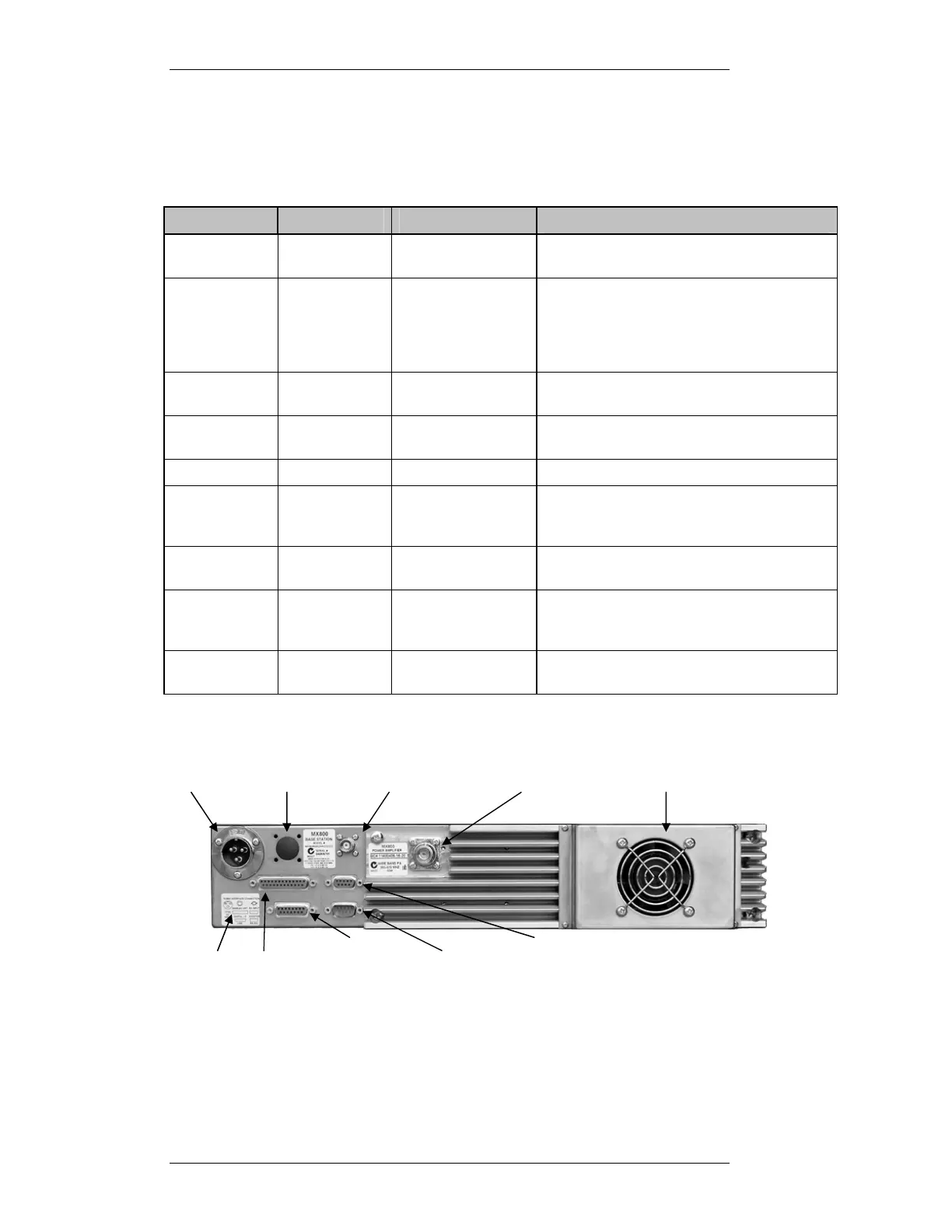
Figure 1-3 MX800 Rear Panel
Thermally
CN8 N-Type
CN7 BNC Rx Input
CN6 Simplex
Relay Output or
N-Type Rx Input
When fitted
CN5 DC
CN2
CN4
CN1 Line
CN3
CN9 RJ45
When fitted