Technical Manual Technical Description
© SPECTRA ENGINEERING 2006 Revision 4.2.3
15
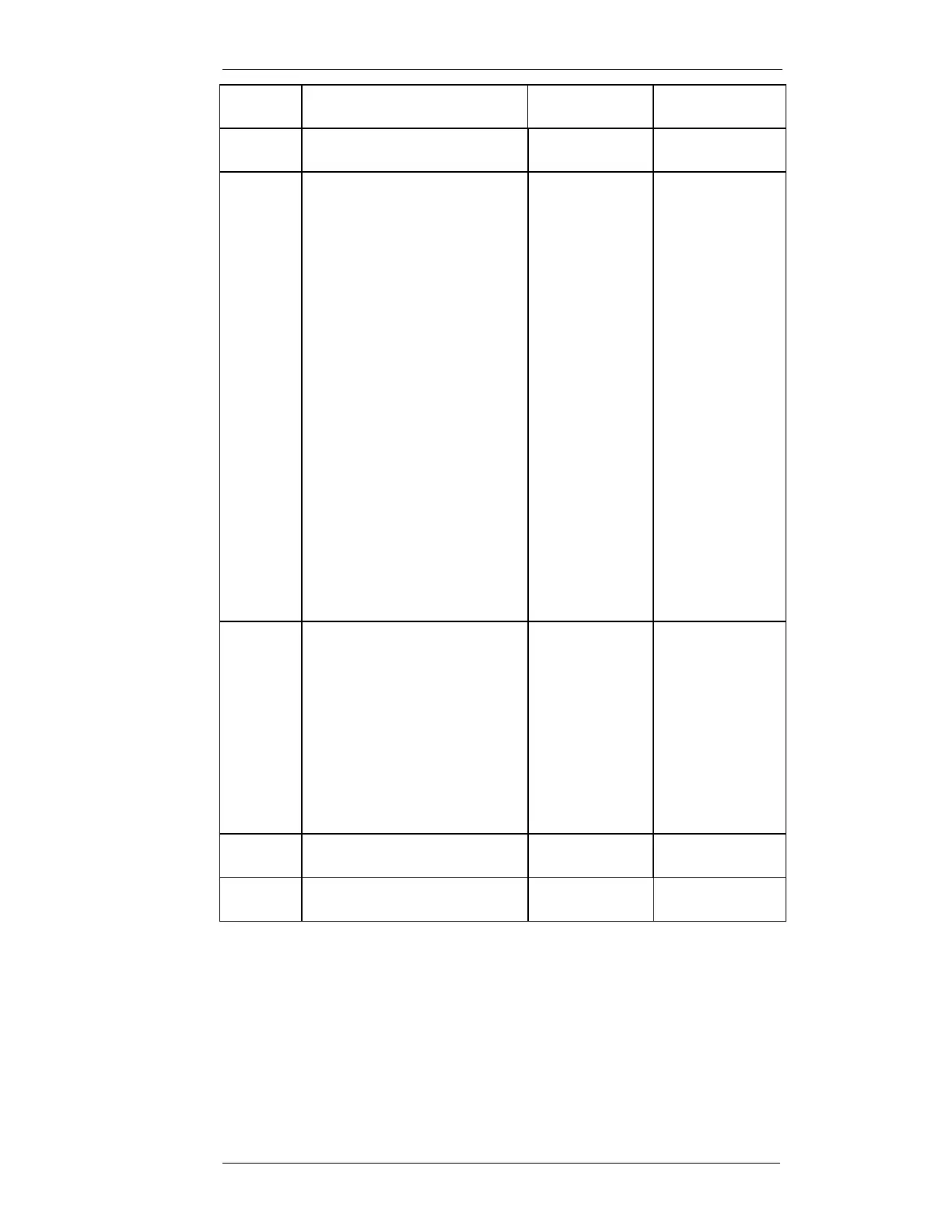
JMP 22 Microphone gain. Fit this jumper
to increase Mic gain 33dB
Low gain Not fitted
JMP 23 Enable tone to speaker. Fit this
jumper to enable tone
Disabled Not fitted
JMP 24 RS232 port termination. This
jumper allows an internal
termination to be selected or not
for bussed RS232 connections.
Up to 16 units may be bussed.
All bussed bases are ‘listeners’ on
the modem RS232 TX port. All
bussed bases have their RS232
TX ports diode to the modem Rx
port.
Normal: Non-bussed mode.
No resistor fitted.
D10 out of circuit.
Master: Bussed mode.
4K7 resistor across D10.
Configure at least one
and no more than four
MX800 in this mode
when multiple units
connected.
Slave: Bussed mode. D10 fitted,
no resistor. Configure
balance of bussed units
in this mode.
Normal 1-2
1-2
2-3
3-4
JMP 25 Mute defeat enable. Mute defeat
cannot be used if RX TALK line
is required. To use mute defeat
remove JMP12 and fit JMP 25.
The control signal polarity can be
inverted by changing the position
of JMP25.
Active low control:
JMP25 2-3
Active high control:
JMP25 1-2
Disabled Not fitted
JMP 26 CTCSS output / TX VF Loopback
control
TX VF
Loopback
2-3
JMP 27 CTCSS input / WB DC-FM input WB DC-FM
input
2-3
Table 2-1 Micro Controller Jumpers
When the MX800 option card is not fitted there is no connection made to
SKK (Aux 2 connector) on the micro controller. Links should be placed
across SKK1-2 (Discriminator audio), SKK11-12 (TX supply) and SKK13-
14 (RX supply). These links are normally fitted in production.