Technical Manual Technical Description
© SPECTRA ENGINEERING 2006 Revision 4.2.3
25
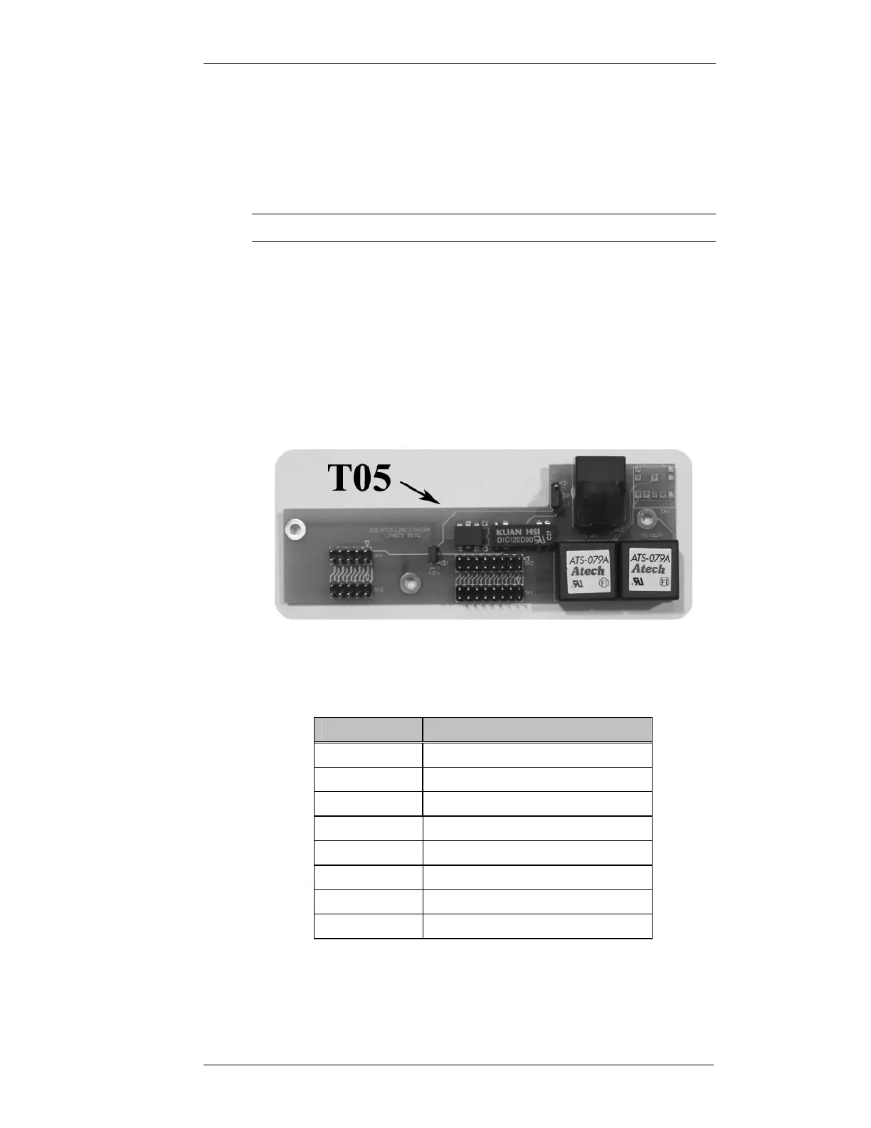
3.5 T05 Balanced and Isolated VF plus E&M
3.5.1 Description
Option T05 provides the balanced and isolated VF I/O as per option T04 as
well as isolated E (PTT) and M (Mute) leads.
Note
Jumpers referred to in the table below are those on this option PCB.
The E lead is opto isolated and may be asserted by applying a DC voltage
between 5V and 48V with any polarity between CN9 Pins 7&8 (JMP1 in
position 2-3, JMP2 removed). Provision is also made to internally source the
activation voltage (+12V DC) in which case the E lead is asserted by
grounding CN9 Pin8 (JMP1 in position 1-2, JMP2 fitted.)
The M lead is relay isolated and the common and normally open contacts are
brought out via CN9. If the internal +12V DC is being used as the activation
voltage for the E lead (JMP1 in position 1-2) then the normally closed contact
is also available at CN9. The relay contacts are rated at 500mA.
Figure 3-4 MX800 Option T05 Balanced & Isolated VF I/O with E&M leads
Pin No
Function
1 600ohm balanced RX VF leg a
2 600ohm balanced RX VF leg b
3 600ohm balanced TX VF leg a
4 600ohm balanced TX VF leg b
5 M Lead common
6 M Lead normally open
7 E Lead leg a/M lead normally closed
8 E Lead leg b
Table 3-2 CN9 Connections