Technical Manual Technical Description
© SPECTRA ENGINEERING 2006 Revision 4.2.3
31
JMP
Function/Description
Option Active
Option Disabled
JMP 1 Low standby current mode
switched exciter power
Out In
JMP 2 Low standby current mode
switched receiver power
Out In
JMP 3 300Hz Elliptic filter 1-2 2-3
JMP 4 RX audio delay 2-3 1-2
Table 3-3 Option PCB Link Settings
Refer circuit diagram CS022-1B
3.8.2 Installation
Components Required:
1. Option board ‘MXOPT’ fitted for VF Delay option. Qty-1
2. 16way female-to-female IDC Cable Assy. Qty-1
3. 3x20mm Standoff posts. Qty-4
Test Equipment Required:
1. Communications Test Set
2. MX800 Radio Interface Box
Method:
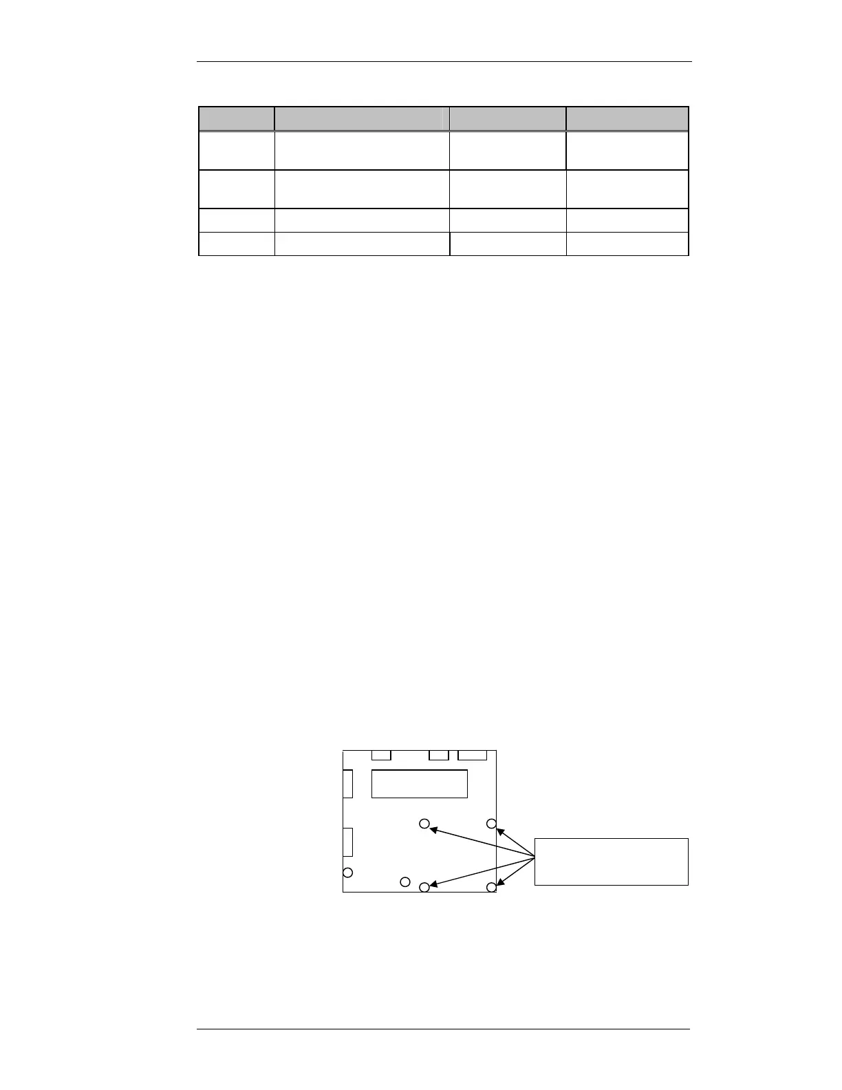
1. Remove the cover to the MX800 radio.
2. Remove qty4 of the Motherboard securing screws as shown.
3. Install the qty 4 3x20mm standoff posts into the vacant screw positions.
4. Remove the Link jumpers off connector SKK.
Motherboard
3x5mm machine
screws to be removed