MX800 Transceiver Technical Manual
© SPECTRA ENGINEERING 2006 Revision 4.2.3
58
3.17.11 T19/26 Pinouts
Table 3-9 CN3 Connections
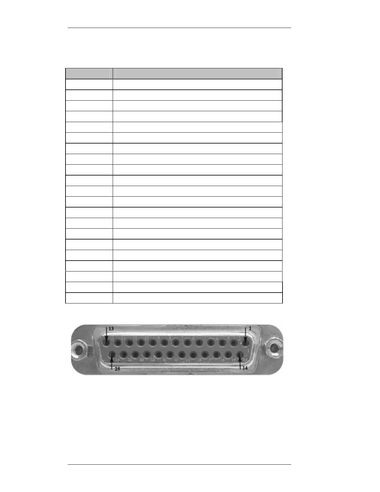
Figure 3-11 CN3 Pin-out Detail (View from Rear of MX800)
CN3 Pin No
Function
11 M2 Lead
24 M2 Lead normally open
25 E2 lead A
12 E2 lead B
13 ETH/ +5V (Set via MX800 JMP15)
1 600ohm balanced RX VF leg a
14 600ohm balanced RX VF leg b
2 600ohm balanced TX VF leg a
15 600ohm balanced TX VF leg b
3 M1 Lead common
16 M1 Lead normally open
4 E1 Lead leg a/M lead normally closed
17 E1 Lead leg b
21 INPUT PORT B. BCD Channel Select Units bit 0. / Binary Bit 0.
8 INPUT PORT B. BCD Channel Select Units bit 1. / Binary Bit 1.
20 INPUT PORT B. BCD Channel Select Units bit 2. / Binary Bit 2.
7 INPUT PORT B. BCD Channel Select Units bit 3. / Binary Bit 3.
19 INPUT PORT B. BCD Channel Select Tens bit 0. / Binary Bit 4.
6 INPUT PORT B. BCD Channel Select Tens bit 1. / Binary Bit 5.
18 INPUT PORT B. BCD Channel Select Tens bit 2. / Binary Bit 6.
5 INPUT PORT B. BCD Channel Select Tens bit 3. / Binary Bit 7.