Technical Manual General Description
© SPECTRA ENGINEERING 2006 Revision 4.2.3
7
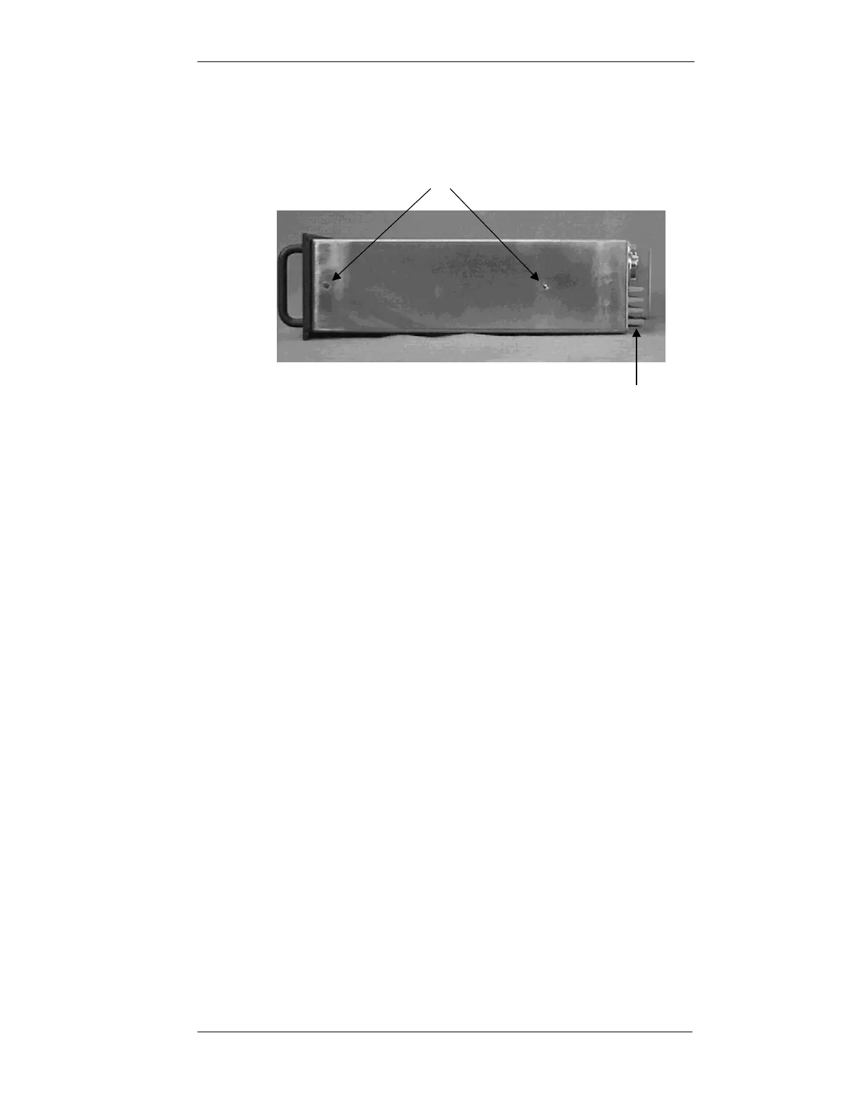
1.1.2 Side Panel
The MX800 side view is illustrated in Figure 1-4 below. Two mounting holes
in each side make provision for fitting a slider rail bracket.
Figure 1-4 MX800 Side Panel
1.2 Module Functional Description
1.2.1 Exciter Module
The Exciter module generates the low level, on frequency, RF transmitter
signal that is later amplified to nominal output power level by the Power
Amplifier module. The exciter consists of a Voltage Controlled Oscillator
(VCO) and associated main RF board, which, in conjunction with the
reference oscillator and the PLL circuitry, forms a two-point modulation
programmable frequency synthesiser. Frequency programming data is
received from the Micro Controller via an 3 wire serial data bus.
The exciter module features a modulation bandwidth from DC with an ultra
wide RF bandwidth of 20MHz to 1000MHz at an average RF output power
of 300mW. To change from one band to another, all that is required is to
change the plug in VCO board and reprogram the radio. No other manual
adjustment or change is required.
Should a high stability reference be required, the exciter can be fitted with a
connector for an external reference oscillator input.
The fractional N synthesiser provides ultra low spurii while still maintaining
fast lock times even at 6.25kHz step size.
An optional built in turn around mixer (TRM) provides advanced diagnostics
such as receiver sensitivity tests.
Mounting Holes for Slide Rails
Sideways Airflow Permits MX800s
to be Stacked in a Rack