Technical Manual Technical Description
© SPECTRA ENGINEERING 2006 Revision 4.2.3
33
micro controller card. The links on the Option card are set as below. This
option is purely a hardware change and no configuration is required using
MXTOOLS.
Note that this options PCB is also used for T08, VF Delay and T10, the Low
Standby Current Mode and all three are independent and may be used
separately or together. If the option PCB is ordered for one particular option
it may or may not be populated for the other options.
JMP
Function/Description
Option Active
Option Disabled
JMP 1 Low standby current mode
switched exciter power
Out In
JMP 2 Low standby current mode
switched receiver power
Out In
JMP 3 300Hz Elliptic filter 1-2 2-3
JMP 4 RX audio delay 2-3 1-2
Table 3-4 Option PCB Link Settings
3.9.2 Installation
Components Required:
1. Option board ‘MXOPT’ fitted for 300Hz HPF Option. Qty-1
2. 16way female-to-female IDC Cable Assy. Qty-1
3. 3x20mm Standoff posts. Qty-4
Test Equipment Required:
1. Communications Test Set
2. MX800 Radio Interface Box
Method:
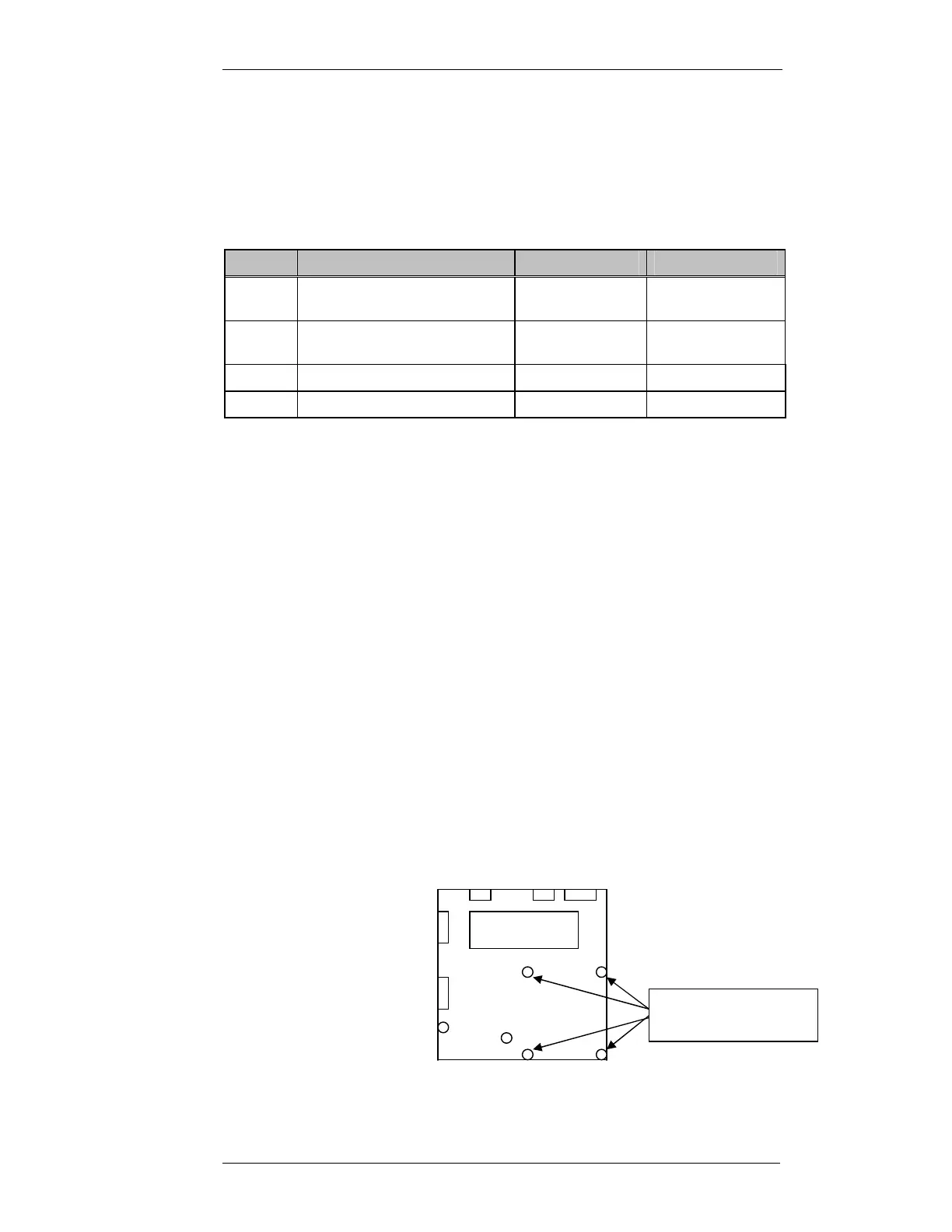
1. Remove the cover to the MX800 radio.
2. Remove qty4 of the Motherboard securing screws as shown.
Motherboard
3x5mm machine
screws to be removed