Technical Manual Technical Description
© SPECTRA ENGINEERING 2006 Revision 4.2.3
23
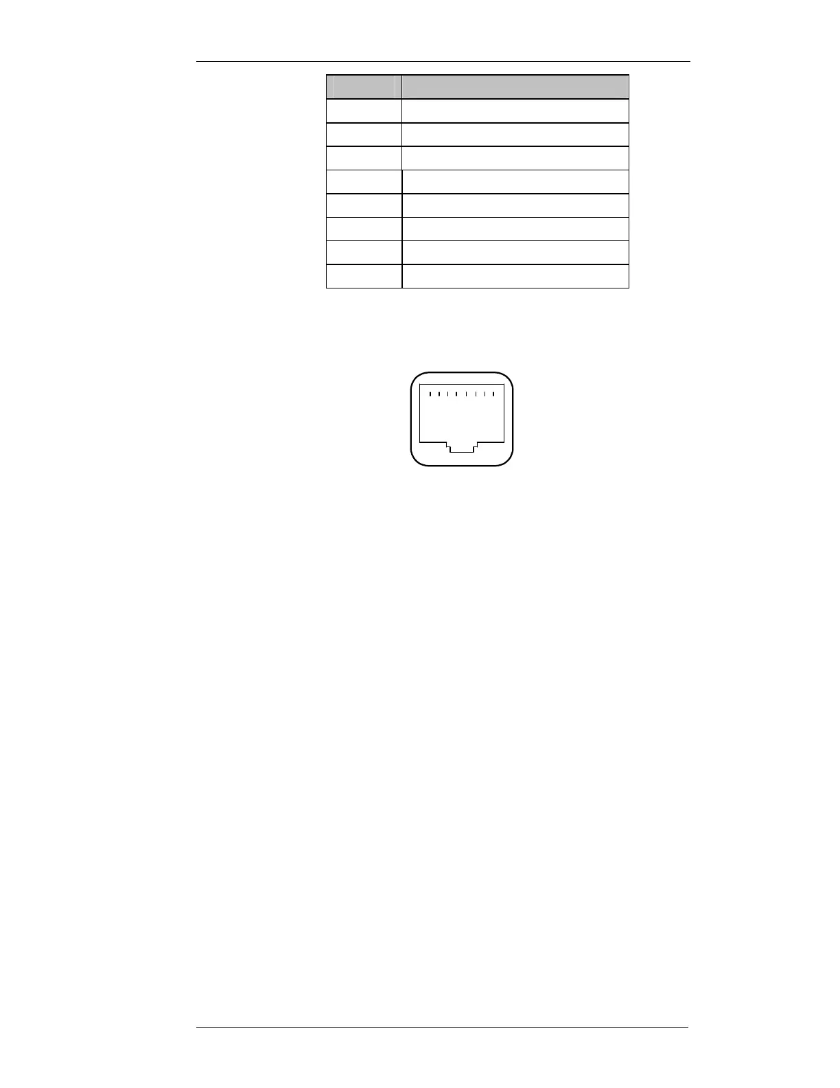
Pin No
Function
1 600ohm balanced RX VF leg a
2 600ohm balanced RX VF leg b
3 600ohm balanced TX VF leg a
4 600ohm balanced TX VF leg b
5 NC
6 NC
7 NC
8 NC
Table 3-1 CN9 Connections
The RJ45 pins are numbered as shown in Figure 3-3 below.
Figure 3-3 CN9 RJ45 Pin-out Detail (View from Rear of MX800)
Refer circuit diagram CS018-1
3.4.2 Installation
Components Required:
1. Option board T04. Qty-1
2. 3x5mm machine screw. Qty-3
3. 10way Female-to-Female connector assy. Qty-1
4. 16way Female-to-Female connector assy. Qty-1
5. Rear connector layout label. Qty-1
Test Equipment Required:
1. Communications Test Set
2. MX800 Radio Interface Box
1 .................. 8