Technical Manual Technical Description
© SPECTRA ENGINEERING 2006 Revision 4.2.3
41
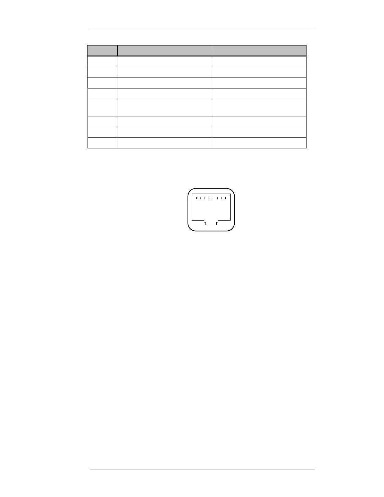
Pin No
Function
Comment
8 PB1 5V CMOS input
7 PB2 5V CMOS input
6 Hook/monitor For quiet base
5 Mic ETH
4 Mic VF in. High or low level Set JMP22 IN for low gain
dynamic Mic
3 Mic PTT. Pulled to +5V via 10K
2 +5 volts out Current limited via 220R
1 Low level muted RX VF Fixed level out.
Table 3-7 MX800 Mic Socket Pinout
The RJ45 pins are numbered as shown in Figure 3-4 below.
Figure 3-9 RJ45 socket viewed from front of MX800
Refer circuit diagram CS001-6 sheet 6 of 6
3.13.2 Installation
CAUTION:
COMPONENTS USED ARE STATIC DAMAGE SENSITIVE!
Components Required:
1. Front Panel and matching Handles. Qty-1
2. Loudspeaker. Qty-1
3. MCP6002D Integrated Circuit. Qty-3
4. TDA8551 Integrated Circuit. Qty-1
5. RJ45 PCB mounted Microphone socket. Qty-1
6. 16mm Volume Pot or SPDT momentary Volume switch. Qty-1
7. 100kohm 10turn PCB mounted squelch potentiometer. Qty-1
8. 100kohm SMD potentiometer. Qty-1
1 .................. 8