MX800 Transceiver Technical Manual
© SPECTRA ENGINEERING 2006 Revision 4.2.3
50
4.
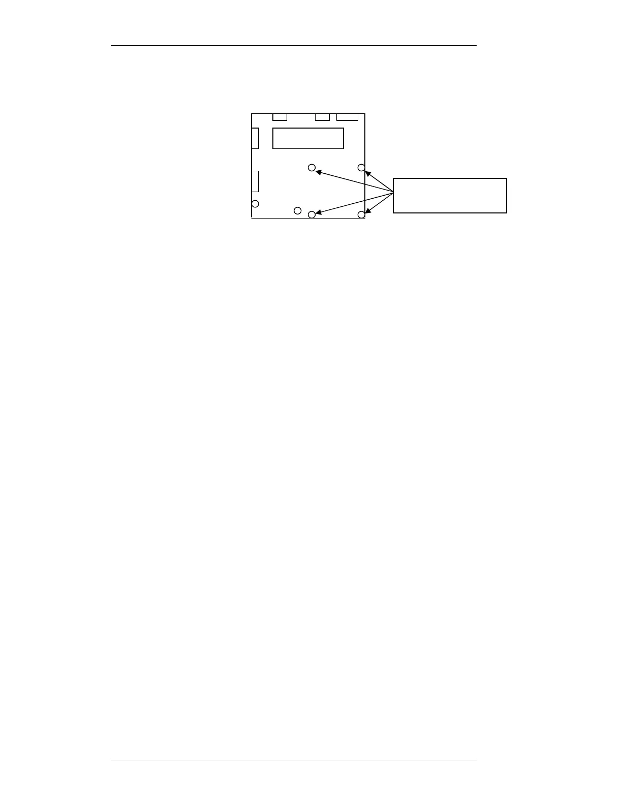
Refit mother board to chassis. Don’t refit the four screws indicated
bellow on the motherboard and fit Qty 4 3x20mm standoff posts in the
positions where the screws where removed.
5. Punch out the Rj45 square on the rear of radio.
6. Install RJ45 daughter board in the rear of chassis, locate the Rj45 socket
into punch hole. Locate mount holes over chassis stand off. Secure with
3x 3mm screws.
7. Remove the Link jumpers off Mother board connector SKK.
8. Install the CABLE IDC SKT - IDC SKT 16W 125mm cable Assy
between connector SKK on the Motherboard and SKK on the Option
board.
9. Install the CABLE IDC SKT-IDC SKT 16WAY 210mm cable Assy.
between connector AUX3 (SKX) on the Motherboard and SKX on the
Option board. This cable will be under option PCB when mounted.
10. Install the Option Printed Circuit Board onto the 4 standoffs with the
16way connector closest to DIP2 on the Motherboard. Secure with the
qty4 3x5mm machine screws previously removed.
11. Install the CABLE IDC SKT-IDC SKT 16WAY 170mm cable Assy.
between connector SKH on the Motherboard and SKH on the Option
board.
12. Install the CABLE IDC SKT-IDC SKT 10WAY 150mm cable Assy.
between connector SKV on the Motherboard and SKV on the Option
board.
13. Remove and replace CN1 with CABLE IDC DB9M-IDC SKT 10W
195mm cable Assy. Connect to SKU on the Option board.
14. Remove and replace CN4 with CABLE IDC DB15F-IDC SKT 16W
210mm cable Assy. Connect to SKH/B on the Option board.
15. Check that the option board jumpers are in the correct positions for
application.
16. See the appropriate application section for Setup procedure.
Motherboard
3x5mm machine
screws to be removed