36 SPEKTRUM NX20 • TRANSMITTER INSTRUCTION MANUAL
EN
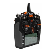
Digital Switch Setup allows you to define the position values of each
digital switch and flight mode switch. The switch can be assigned to
a channel in the Channel Input Config function, and the output of the
channel set in the Digital Input Setup screen. Additionally, the Flight
Mode switch can have position values defined for each flight mode,
and may be used as a mix input or channel input source, with the
values defined in Digital Input Setup.
To use the Digital Switch Setup function:
1. Enter the Digital Input Setup screen, and press the roller with
Inhibit selected.
2. Roll to select the switch or Flight Mode switch and press to
select.
3. Roll to the desired position to adjust, and press the roller to
select.
4. Roll to select the desired value, then press to select.
5. Repeat step 4 and 5 for all positions that you wish to adjust.
6. If you want to select a switch to control a channel, roll to
select Channel: Inhibit on the bottom of the screen and press
the roller. This will take you to the Channel Input Config screen
to assign a channel to a switch.
7. Repeat 2 through 6 for all switches desired.
IMPORTANT: After you exit the Digital Input Setup screen, the
return screen will show Inhibit at the top of the screen. If you wish
to adjust a previously set value, select the switch and the previously
set values can then be viewed and re-adjusted as desired.
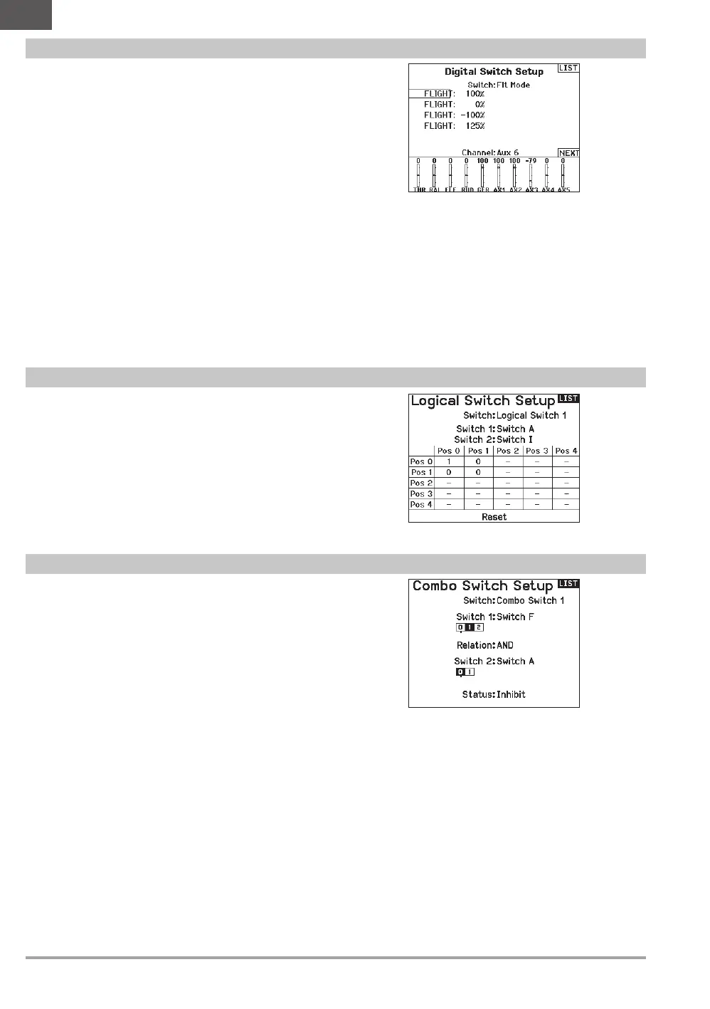
Logical Switch Setup enables you to use two inputs to select as
many as nine different switch positions. There are 16 logical switch
setups available. Once the table is set up and defined, you can select
the logical switch positions anywhere in the programming menus
where you can select a switch
To use the Logical Switch Setup function:
1. Enter the Logical Switch Setup screen, and select the logical
switch you want to use.
2. Select the two input devices.
3. Explore all the switch/stick positions of the two input devices
and define the output values for all the cells on the table.
Digital Switch Setup
Logical Switch Setup
Combo Switch Setup
Combo Switch Setup enables you to use two input devices to
activate a switch, with an AND/OR option to tie the two input devices
together. Once this page is defined you can select Combo Switch
positions anywhere in the programming menus where you can select
a switch.
To use the Combo Switch Setup function:
1. Select the first switch, define the switch position where you
want the function to be active.
2. Select AND/OR
3. Select the second switch and define the switch position(s) you
want the function to be active.
 Loading...