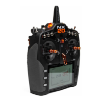
9SPEKTRUM NX20 • TRANSMITTER INSTRUCTION MANUAL
EN
• Scroll the scroll wheel to move through the screen content or
change programming values. Press the scroll wheel to make
a selection.
• Use the Back button to go to the previous screen (for example,
to go from the Mixing Screen to the Function List).
• Use the Clear button to return a selected value on a screen to
the default setting.
• Direct Model Access enables you to access the Model Select
screen without powering off the transmitter. Anytime the
transmitter power is on, press the Clear and Back buttons to
access the Model Select screen.
• Press and hold the scroll wheel while powering on the
transmitter to show the System Setup list. No radio
transmission occurs when a System Setup screen is
displayed, preventing accidental damage to linkages and
servos during changes to programming.
• Scroll from the main screen to view telemetry screens and the
servo monitor.
• The Main Screen appears when you power on the transmitter.
Press the scroll wheel once to display the Function List.
• When you want to change a value in a screen for a particular
control position, move the control to the desired position to
highlight the value you want to change, such as 0/1/2, up/
down or left/right.
Enter, Choose
or Exit
Move between
options or change
value in an option
Hold for 3
seconds and
release to move to
the Main Screen
Scroll HoldPress
TIP: The tick mark below shows the current switch position.
Roll to select the box, then click the scroll wheel to change the
selected box. When the selected box is black it indicates the
value or condition will act on that position, white means that
position is not selected, and grey means that position is not
assigned to anything (with the default color palete).
The following example shows the switch for Rates is in the 1
position (tick below the box), and the grey means the 1 switch
position is not assigned to anything.
In order to reset back to default; select the switch position first,
then set the curve number to match the switch position, then set
the box for that switch position to black.
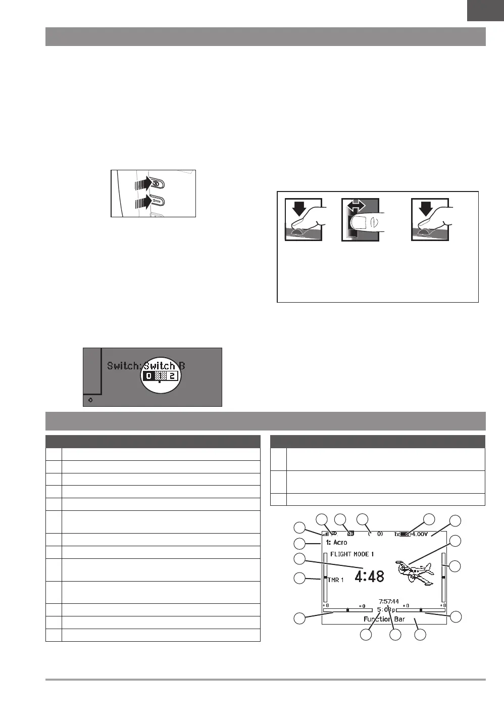
NAVIGATION
MAIN SCREEN
Function
1 Model name
2 Forward signal strength as reported by the telemetry
3 Telemetry data being recorded
4 Smart device connected
5 Throttle stick position (0-100)
6
Digital battery voltage (an alarm sounds and the screen flashes
if the battery charge gets down to 3.2V.)
7 Modulation type, shown after binding (DSMX/DSM2)
8 Model avatar
9
Elevator trim (Mode 2, 4)
Throttle trim (Mode 1, 3)
10
Aileron trim (Mode 1, 2)
Rudder trim (Mode 3, 4)
11 Function bar
12 Transmitter system clock
13 Time
Function
14
Rudder trim (Mode 1, 2)
Aileron trim (Mode 3, 4)
15
Throttle trim (Mode 2, 4)
Elevator trim (Mode 1, 3)
16 Model timer
8
7
6
3
5
15
16
2
9
13
4
14
10
11
12
1
 Loading...