UM2222 Rev 2 71/76
UM2222 Functional description of the STM32H745I-DISCO demonstration modules
75
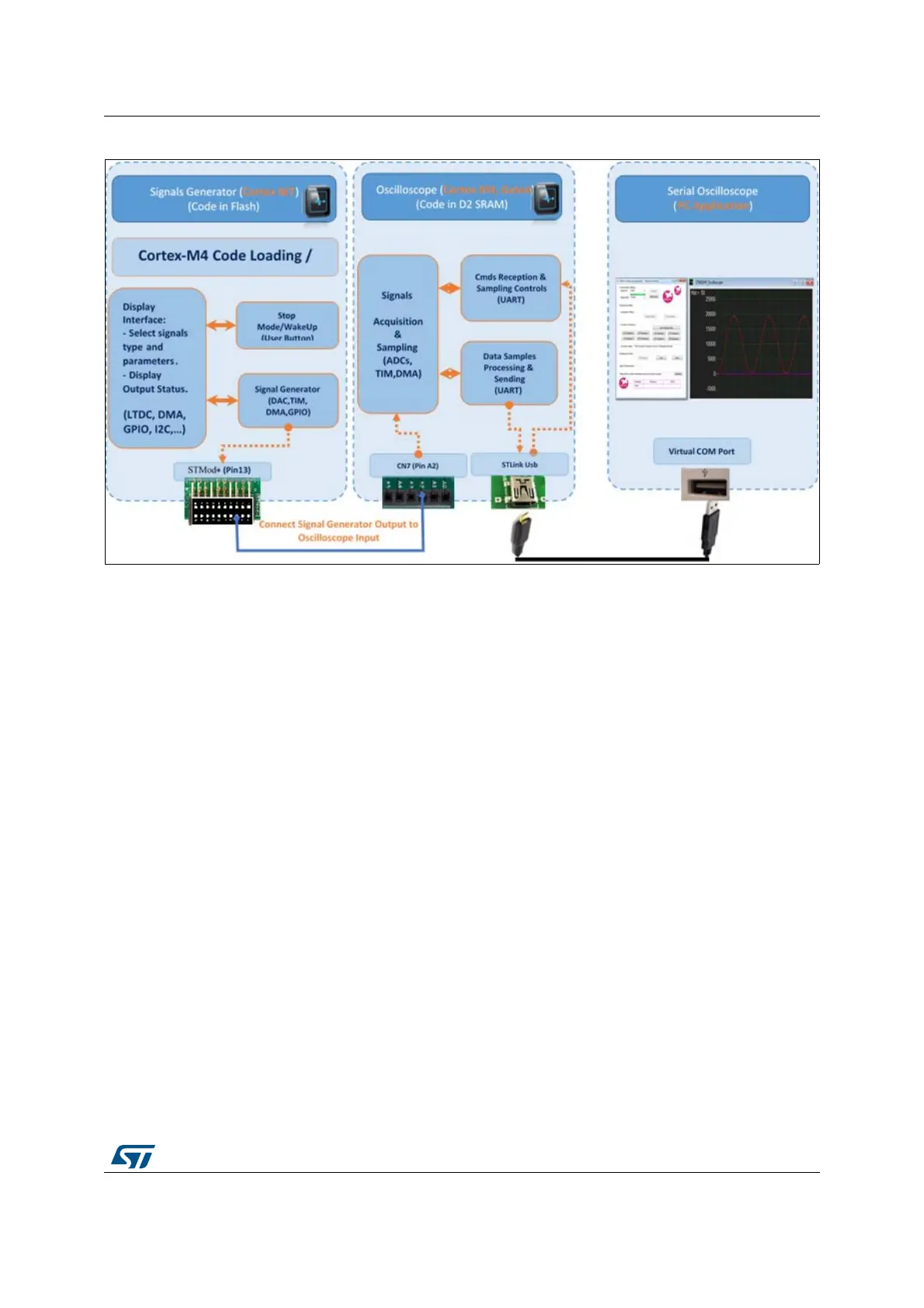
Figure 72. Oscilloscope and signals generator overview
9.4.3 Hardware and software setup
1. Install the PC GUI application on your PC
• This application is used to:
a) Configure the ADC parameters
b) Receive and visualize samples acquired by the ADC and sent by the Cortex-M4
• The communication between the PC application and the STM32H745I-DISCO is
ensured by the ST-Link USB connector used as Virtual COM port
• Connect the STM32H745I-DISCO USB ST-LINK port to the PC
2. STM32H745I-DISCO HW setup
In order to inject the signal generator output to the oscilloscope input, use an external wire
connection from the on-board STMod+ (pin13) to CN7 (pin A2) as shown in
Figure 73:
• STMod+ (pin13): the signal generator (DAC) output pin
• CN7 (pin A2): this is the Oscilloscope (ADC) input pin