Functional description of the STM32H745I-DISCO demonstration modules UM2222
72/76 UM2222 Rev 2
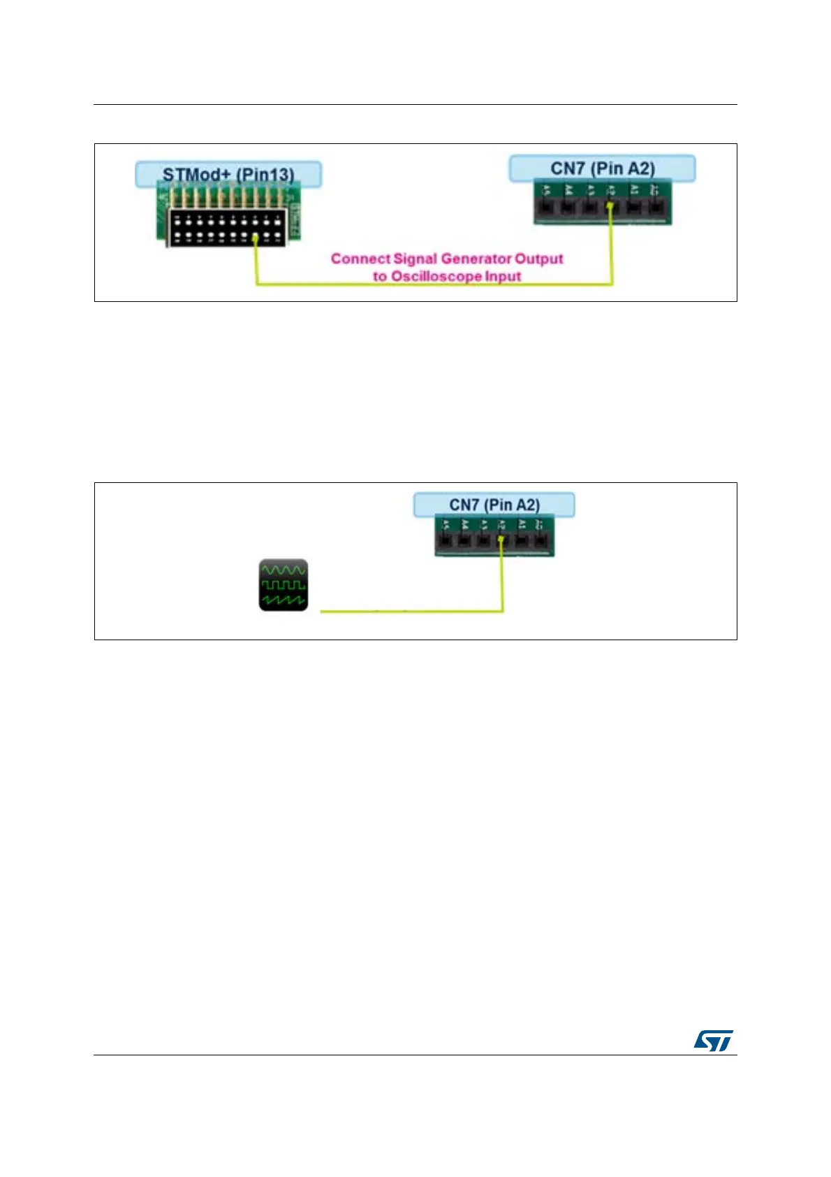
Figure 73. Signal generator to oscilloscope connection
The user may choose to inject his own signal to the oscilloscope, in this case:
• Remove the STMod+ (pin13) to CN7 (pin A2) connection
• Inject the signal to be sampled by the oscilloscope: connect external signal source to
CN7 (pin A2)
• The signal parameter must be as follow:
– Amplitude: from 0 to 3.3 V
– Frequency: up to 1 MHz
Figure 74. External signal to oscilloscope connection
9.4.4 How to use
1. PC Software Side:
Start the PC oscilloscope application
• In the Communication Settings
– Select the Serial Port corresponding to the ST-Link Virtual COM
– Select the Baud Rate 115200
– Click on Connect
Click on Start Scope to visualize the input signal.