EasyManua.ls Logo

ST STM32F4 Series User Manual

ST STM32F4 Series
262 pages
To Next Page IconTo Next Page
To Previous Page IconTo Previous Page
Page #143 background imageLoading...
Page #143 background image
PM0214 Rev 9 143/262
PM0214 The STM32 Cortex-M4 instruction set
261
B cond label is the only conditional instruction that can be either inside or outside an IT
block. All other branch instructions must be conditional inside an IT block, and must be
unconditional outside the IT block, see IT on page 145.
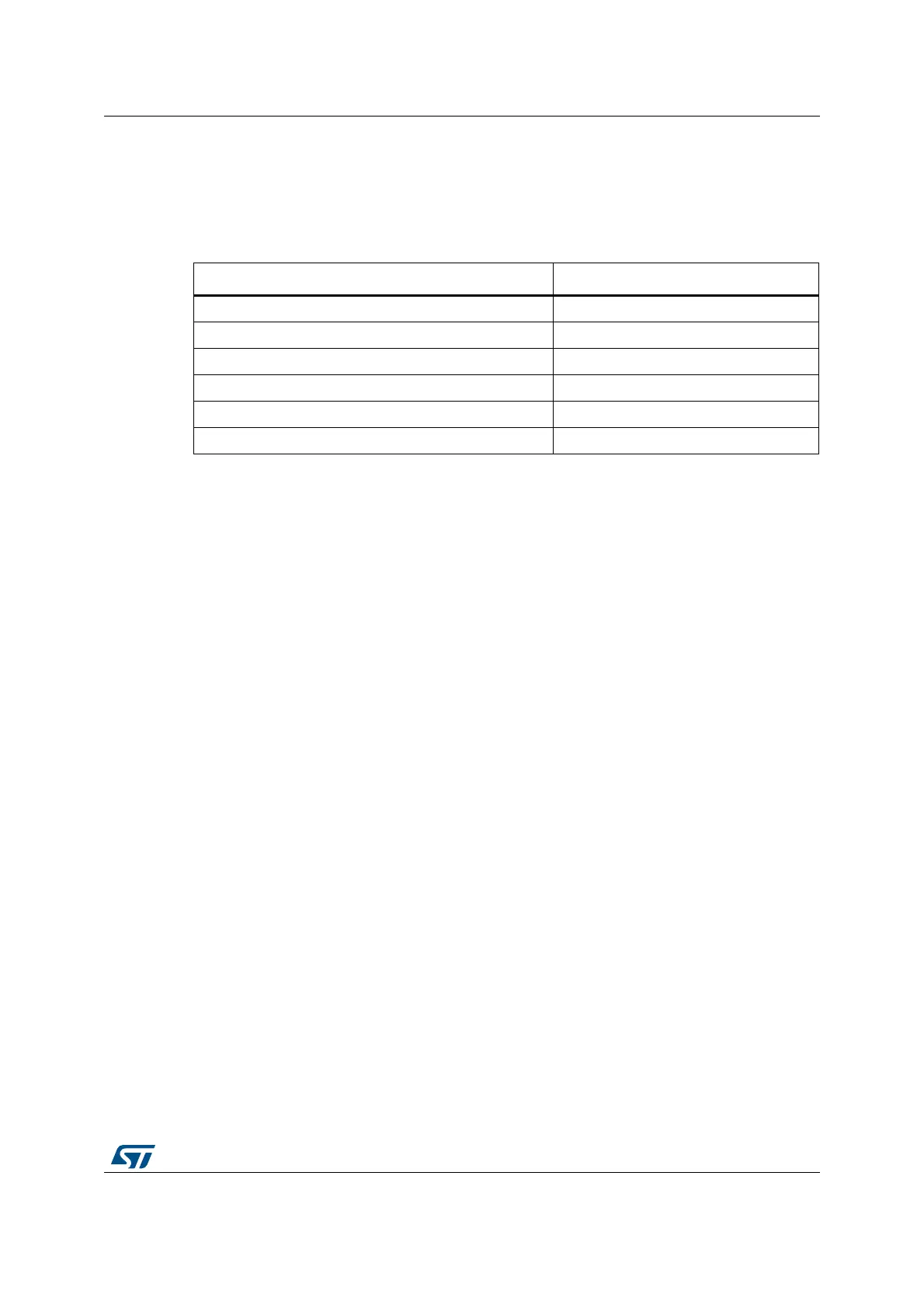
Table 34 shows the ranges for the various branch instructions.
You might have to use the .W suffix to get the maximum branch range. See Instruction width
selection on page 68.
Restrictions
The restrictions are:
Do not use PC in the BLX instruction
For BX and BLX, bit[0] of Rm must be 1 for correct execution but a branch occurs to the
target address created by changing bit[0] to 0
When any of these instructions is inside an IT block, it must be the last instruction of the
IT block.
Bcond is the only conditional instruction that is not required to be inside an IT block.
However, it has a longer branch range when it is inside an IT block.
Condition flags
These instructions do not change the flags.
Examples
B loopA ; Branch to loopA
BLE ng ; Conditionally branch to label ng
B.W target ; Branch to target within 16MB range
BEQ target ; Conditionally branch to target
BEQ.W target ; Conditionally branch to target within 1MB
BL funC ; Branch with link (Call) to function funC, return address
; stored in LR
BX LR ; Return from function call
BXNE R0 ; Conditionally branch to address stored in R0
Table 34. Branch ranges
Instruction Branch range
B label 16 MB to +16 MB
Bcond label (outside IT block) 1 MB to +1 MB
Bcond label (inside IT block) 16 MB to +16 MB
BL{cond} label 16 MB to +16 MB
BX{cond} Rm Any value in register
BLX{cond} Rm Any value in register

Table of Contents

Other manuals for ST STM32F4 Series

Question and Answer IconNeed help?

Do you have a question about the ST STM32F4 Series and is the answer not in the manual?

ST STM32F4 Series Specifications

General IconGeneral
SeriesSTM32F4
CoreARM Cortex-M4
Clock SpeedUp to 180 MHz
Flash MemoryUp to 2 MB
RAMUp to 384 KB
Operating Voltage1.8 V to 3.6 V
DAC12-bit, up to 2 channels
TimersUp to 17 timers
Communication InterfacesUSB, CAN, SPI, I2C, USART, Ethernet
Operating Temperature-40°C to 85°C
PackageLQFP, WLCSP, BGA

Summary

Introduction to the STM32 Cortex-M4 Programming Manual

Cortex-M4 Processor Features and Benefits

Summarizes key advantages: outstanding performance, enhanced debug, efficient core, low power, and security.

Reference Documents for STM32 Cortex-M4

Lists datasheets and reference manuals available from STMicroelectronics website for further details.

About this document

Typographical Conventions Used

Explains conventions for highlighting important notes, cross-references, and code elements.

Abbreviations for Registers

Lists common abbreviations used in register descriptions, such as (rw), (r), and (w).

STM32 Cortex-M4 Processor and Core Peripherals Overview

Introduces the Cortex-M4 processor, its architecture, and integrated core peripherals.

The Cortex-M4 Processor

Cortex-M4 Programmers Model

Describes processor modes, privilege levels, execution states, and stack usage.

Cortex-M4 Memory Model

Explains the memory map, access behavior, and bit-banding features.

Cortex-M4 Exception Model

Covers exception states, types, handlers, priorities, and grouping mechanisms.

The STM32 Cortex-M4 Instruction Set

Instruction Set Summary and Syntax

Lists supported instructions, syntax conventions, and flexible operand usage.

Memory Access Instructions

Details instructions for loading and storing data from memory.

General Data Processing Instructions

Covers arithmetic, logical, shift, and data manipulation instructions.

Multiply and Divide Instructions

Explains signed/unsigned multiply, accumulate, divide, and saturation instructions.

Saturating Instructions

Describes instructions performing saturation arithmetic on signed/unsigned values.

Core Peripherals

Nested Vectored Interrupt Controller (NVIC)

Details the NVIC's interrupt handling, priority levels, and registers.

System Control Block (SCB) Registers

Explains SCB registers for system control, configuration, and exception reporting.

SysTick Timer (STK) Functionality

Describes the SysTick timer for system timing and RTOS tick generation.

Document Revision History

Related product manuals