EasyManua.ls Logo

ST STM32F4 Series User Manual

ST STM32F4 Series
262 pages
To Next Page IconTo Next Page
To Previous Page IconTo Previous Page
Page #47 background image
PM0214 Rev 9 47/262
PM0214 The Cortex-M4 processor
261
2.4.3 Fault status registers and fault address registers
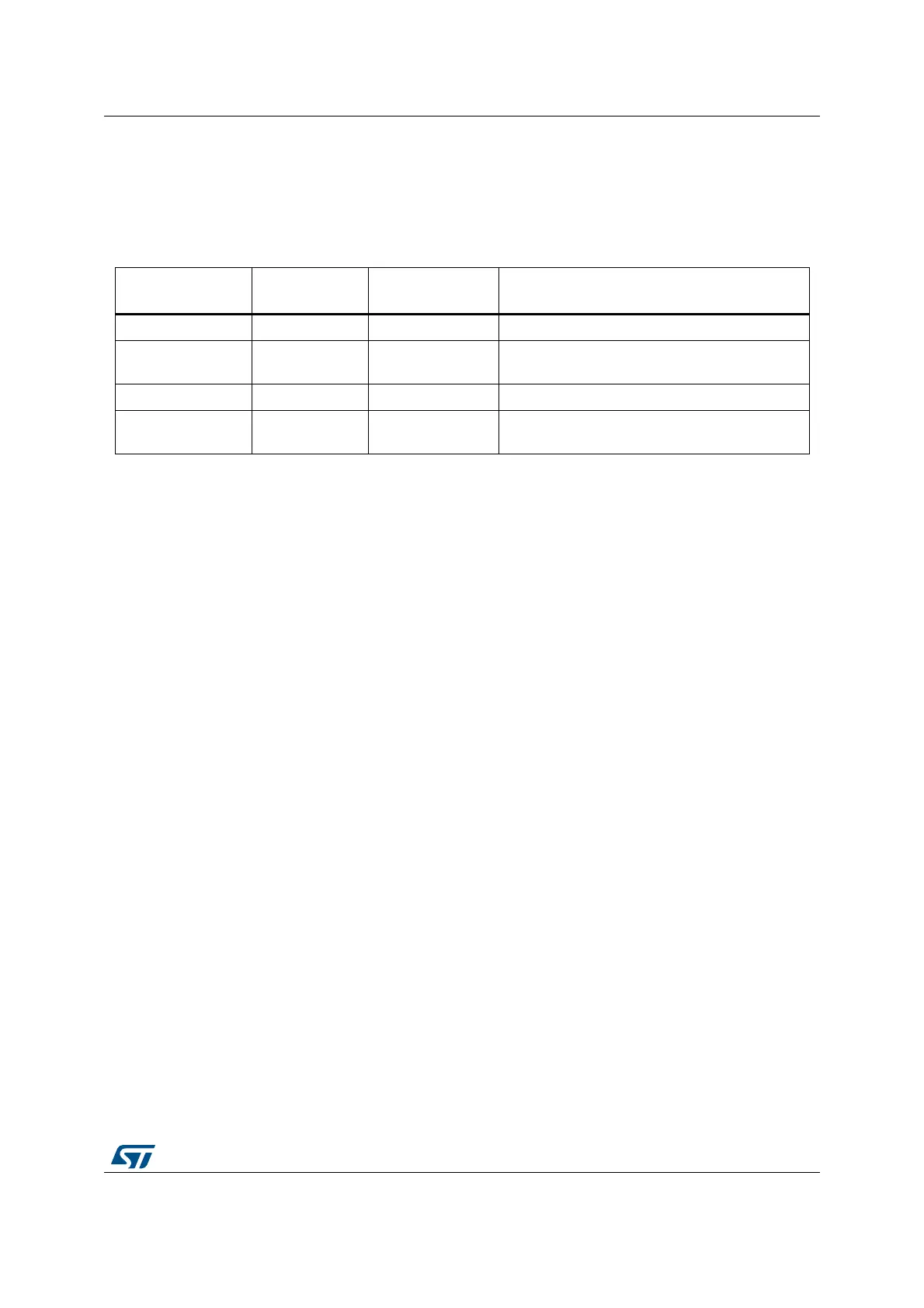
The fault status registers indicate the cause of a fault. For bus faults and memory
management faults, the fault address register indicates the address accessed by the
operation that caused the fault, as shown in Table 20.
2.4.4 Lockup
The processor enters a lockup state if a hard fault occurs when executing the NMI or hard
fault handlers. When the processor is in lockup state it does not execute any instructions.
The processor remains in lockup state until either:
It is reset
An NMI occurs
It is halted by a debugger
If lockup state occurs from the NMI handler a subsequent NMI does not cause the
processor to leave lockup state.
2.5 Power management
The STM32 and Cortex-M4 processor sleep modes reduce power consumption:
Sleep mode stops the processor clock. All other system and peripheral clocks may still
be running.
Deep sleep mode stops most of the STM32 system and peripheral clocks. At product
level, this corresponds to either the Stop or the Standby mode. For more details, please
refer to the “Power modes” Section in the STM32 reference manual.
The SLEEPDEEP bit of the SCR selects which sleep mode is used, as described in System
control register (SCR) on page 230. For more information about the behavior of the sleep
modes see the STM32 product reference manual.
This section describes the mechanisms for entering sleep mode, and the conditions for
waking up from sleep mode.
Table 20. Fault status and fault address registers
Handler Status register
name
Address register
name
Register description
Hard fault HFSR - Hard fault status register (HFSR) on page 241
Memory
management fault
MMFSR MMFAR
Memory management fault address register
(MMFAR) on page 242
Bus fault BFSR BFAR Bus fault address register (BFAR) on page 242
Usage fault UFSR -
Configurable fault status register (CFSR;
UFSR+BFSR+MMFSR) on page 237

Table of Contents

Other manuals for ST STM32F4 Series

Question and Answer IconNeed help?

Do you have a question about the ST STM32F4 Series and is the answer not in the manual?

ST STM32F4 Series Specifications

General IconGeneral
SeriesSTM32F4
CoreARM Cortex-M4
Clock SpeedUp to 180 MHz
Flash MemoryUp to 2 MB
RAMUp to 384 KB
Operating Voltage1.8 V to 3.6 V
DAC12-bit, up to 2 channels
TimersUp to 17 timers
Communication InterfacesUSB, CAN, SPI, I2C, USART, Ethernet
Operating Temperature-40°C to 85°C
PackageLQFP, WLCSP, BGA

Summary

Introduction to the STM32 Cortex-M4 Programming Manual

Cortex-M4 Processor Features and Benefits

Summarizes key advantages: outstanding performance, enhanced debug, efficient core, low power, and security.

Reference Documents for STM32 Cortex-M4

Lists datasheets and reference manuals available from STMicroelectronics website for further details.

About this document

Typographical Conventions Used

Explains conventions for highlighting important notes, cross-references, and code elements.

Abbreviations for Registers

Lists common abbreviations used in register descriptions, such as (rw), (r), and (w).

STM32 Cortex-M4 Processor and Core Peripherals Overview

Introduces the Cortex-M4 processor, its architecture, and integrated core peripherals.

The Cortex-M4 Processor

Cortex-M4 Programmers Model

Describes processor modes, privilege levels, execution states, and stack usage.

Cortex-M4 Memory Model

Explains the memory map, access behavior, and bit-banding features.

Cortex-M4 Exception Model

Covers exception states, types, handlers, priorities, and grouping mechanisms.

The STM32 Cortex-M4 Instruction Set

Instruction Set Summary and Syntax

Lists supported instructions, syntax conventions, and flexible operand usage.

Memory Access Instructions

Details instructions for loading and storing data from memory.

General Data Processing Instructions

Covers arithmetic, logical, shift, and data manipulation instructions.

Multiply and Divide Instructions

Explains signed/unsigned multiply, accumulate, divide, and saturation instructions.

Saturating Instructions

Describes instructions performing saturation arithmetic on signed/unsigned values.

Core Peripherals

Nested Vectored Interrupt Controller (NVIC)

Details the NVIC's interrupt handling, priority levels, and registers.

System Control Block (SCB) Registers

Explains SCB registers for system control, configuration, and exception reporting.

SysTick Timer (STK) Functionality

Describes the SysTick timer for system timing and RTOS tick generation.

Document Revision History

Related product manuals