EasyManua.ls Logo

ST STM32F4 Series User Manual

ST STM32F4 Series
262 pages
To Next Page IconTo Next Page
To Previous Page IconTo Previous Page
Page #34 background imageLoading...
Page #34 background image
The Cortex-M4 processor PM0214
34/262 PM0214 Rev 9
Reading a word in the alias region:
0x00000000 indicates that the targeted bit in the bit-band region is set to zero
0x00000001 indicates that the targeted bit in the bit-band region is set to 1
Directly accessing a bit-band region
Behavior of memory accesses on page 30 describes the behavior of direct byte, halfword,
or word accesses to the bit-band regions.
2.2.6 Memory endianness
The processor views memory as a linear collection of bytes numbered in ascending order
from zero. For example, bytes 0-3 hold the first stored word, and bytes 4-7 hold the second
stored word.
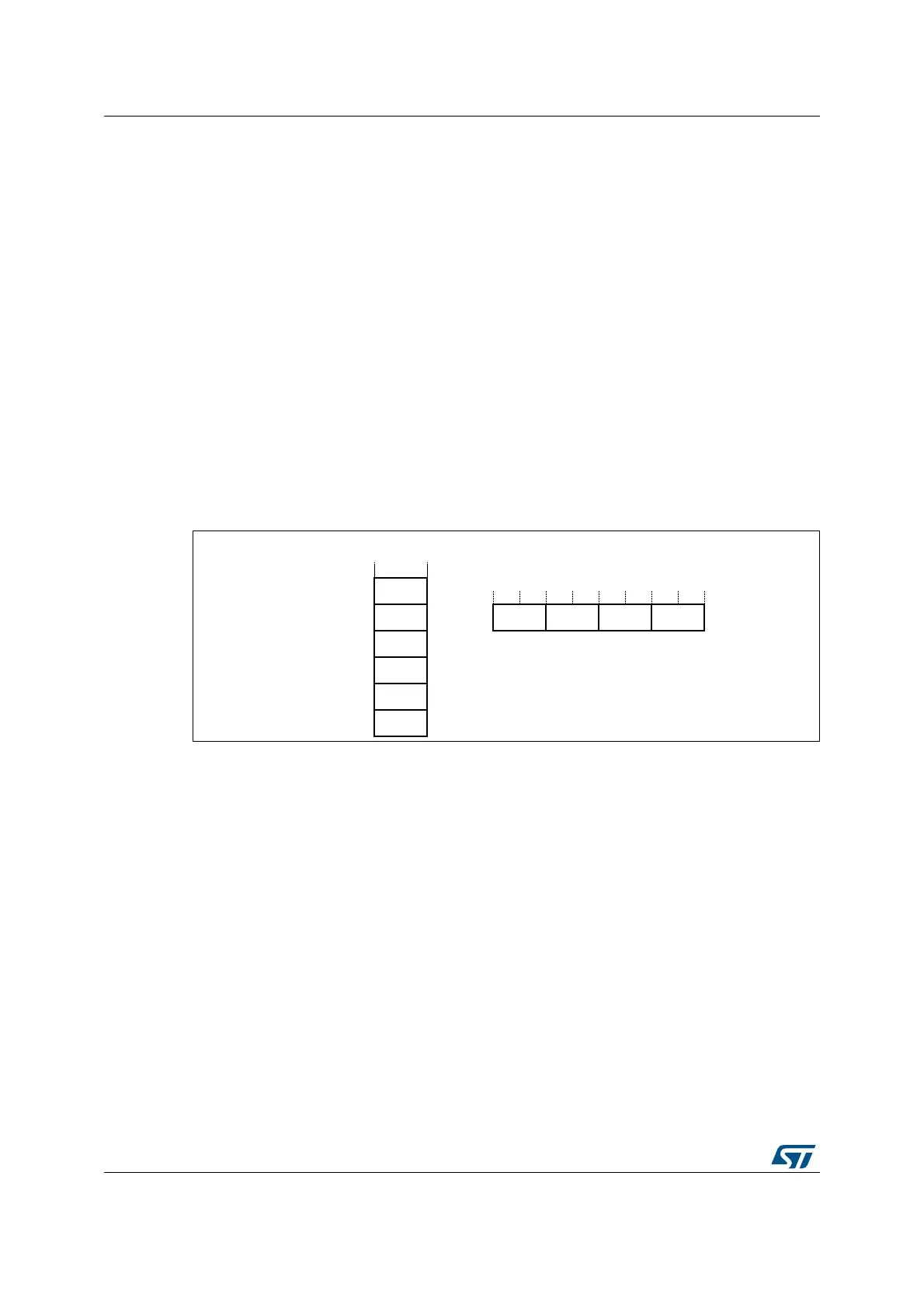
Little-endian format
In little-endian format, the processor stores the least significant byte of a word at the lowest-
numbered byte, and the most significant byte at the highest-numbered byte. See Figure 10
for an example.
Figure 10. Little-endian example
2.2.7 Synchronization primitives
The Cortex-M4 instruction set includes pairs of synchronization primitives. These provide a
non-blocking mechanism that a thread or process can use to obtain exclusive access to a
memory location. Software can use them to perform a guaranteed read-modify-write
memory update sequence, or for a semaphore mechanism.
A pair of synchronization primitives comprises:
Load-Exclusive instruction: used to read the value of a memory location, requesting
exclusive access to that location.
Store-Exclusive instruction: used to attempt to write to the same memory location,
returning a status bit to a register. If this bit is:
0: the thread or process gained exclusive access to memory, and the write succeeds.
1: the thread or process did not gain exclusive access to memory, and no write is
performed.
0HPRU\ 5HJLVWHU
$GGUHVV$
$
OVE\WH
PVE\WH
$
$
%%% %
    
%
%
%
%

Table of Contents

Other manuals for ST STM32F4 Series

Question and Answer IconNeed help?

Do you have a question about the ST STM32F4 Series and is the answer not in the manual?

ST STM32F4 Series Specifications

General IconGeneral
SeriesSTM32F4
CoreARM Cortex-M4
Clock SpeedUp to 180 MHz
Flash MemoryUp to 2 MB
RAMUp to 384 KB
Operating Voltage1.8 V to 3.6 V
DAC12-bit, up to 2 channels
TimersUp to 17 timers
Communication InterfacesUSB, CAN, SPI, I2C, USART, Ethernet
Operating Temperature-40°C to 85°C
PackageLQFP, WLCSP, BGA

Summary

Introduction to the STM32 Cortex-M4 Programming Manual

Cortex-M4 Processor Features and Benefits

Summarizes key advantages: outstanding performance, enhanced debug, efficient core, low power, and security.

Reference Documents for STM32 Cortex-M4

Lists datasheets and reference manuals available from STMicroelectronics website for further details.

About this document

Typographical Conventions Used

Explains conventions for highlighting important notes, cross-references, and code elements.

Abbreviations for Registers

Lists common abbreviations used in register descriptions, such as (rw), (r), and (w).

STM32 Cortex-M4 Processor and Core Peripherals Overview

Introduces the Cortex-M4 processor, its architecture, and integrated core peripherals.

The Cortex-M4 Processor

Cortex-M4 Programmers Model

Describes processor modes, privilege levels, execution states, and stack usage.

Cortex-M4 Memory Model

Explains the memory map, access behavior, and bit-banding features.

Cortex-M4 Exception Model

Covers exception states, types, handlers, priorities, and grouping mechanisms.

The STM32 Cortex-M4 Instruction Set

Instruction Set Summary and Syntax

Lists supported instructions, syntax conventions, and flexible operand usage.

Memory Access Instructions

Details instructions for loading and storing data from memory.

General Data Processing Instructions

Covers arithmetic, logical, shift, and data manipulation instructions.

Multiply and Divide Instructions

Explains signed/unsigned multiply, accumulate, divide, and saturation instructions.

Saturating Instructions

Describes instructions performing saturation arithmetic on signed/unsigned values.

Core Peripherals

Nested Vectored Interrupt Controller (NVIC)

Details the NVIC's interrupt handling, priority levels, and registers.

System Control Block (SCB) Registers

Explains SCB registers for system control, configuration, and exception reporting.

SysTick Timer (STK) Functionality

Describes the SysTick timer for system timing and RTOS tick generation.

Document Revision History

Related product manuals