Boot configuration AN4661
28/54 DocID027559 Rev 5
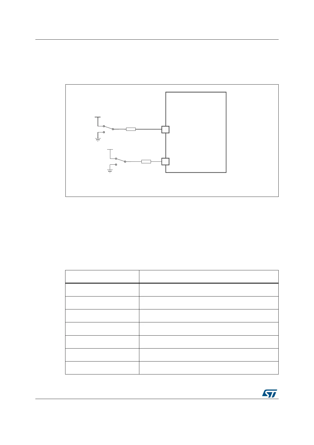
4.2 Boot pin connection
Figure 20 shows the external connection required to select the boot memory of the
STM32F7 Series.
Figure 20. Boot mode selection implementation example
1. Resistor values are given only as a typical example.
4.3 System bootloader mode
The embedded bootloader code is located in the system memory. It is programmed by ST
during production. It is used to reprogram the Flash memory using one of the following serial
interfaces.
Table 3 shows the supported communication peripherals by the system bootloader.
9''
%227
%227
NRKPV
670)[[[[
069
9''
NRKPV
Table 3. STM32F7 Series bootloader communication peripherals
Bootloader peripherals STM32F7 Series
DFU USB OTG FS (PA11 / PA12) in device mode
USART1 PA9 / PA10
USART3 PB10 / PB11 and PC10 / PC11
CAN1
(1)
PB8/PB9
CAN2
(2)
PB5 / PB13
I2C1 PB6 / PB9
I2C2 PF0 / PF1
 Loading...


