DocID027559 Rev 5 29/54
AN4661 Debug management
53
5 Debug management
5.1 Introduction
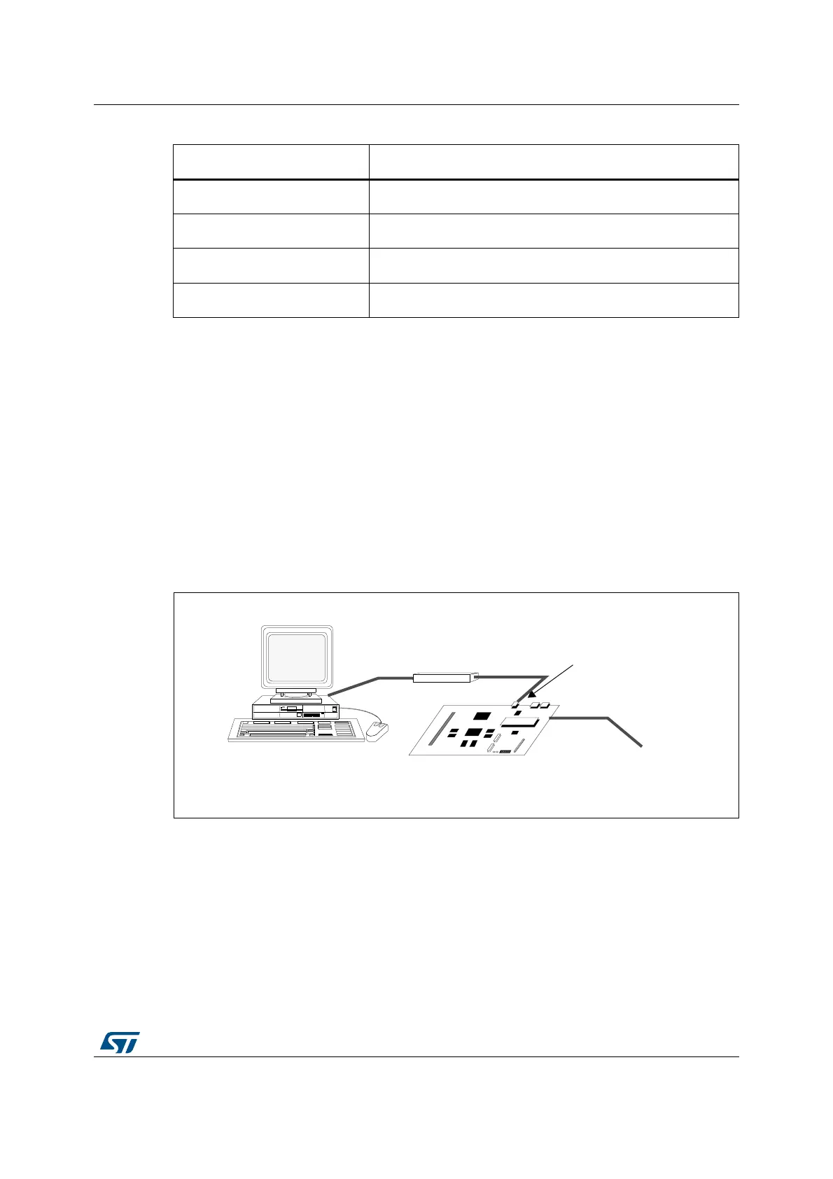
The host/target interface is the hardware equipment that connects the host to the application
board. This interface is made of three components: a hardware debug tool, a JTAG or SW
connector and a cable connecting the host to the debug tool.
Figure 21 shows the
connection of the host to the evaluation board.
Figure 21. Host to board connection
5.2 SWJ debug port (serial wire and JTAG)
The core of the STM32F7 Series integrates the Serial Wire / JTAG Debug Port (SWJ-DP). It
is an ARM
®
standard CoreSight debug port that combines a JTAG-DP (5-pin) interface and
a SW-DP (2-pin) interface.
• The JTAG Debug Port (JTAG-DP) provides a 5-pin standard JTAG interface to the
AHP-AP port.
• The Serial Wire Debug Port (SW-DP) provides a 2-pin (clock + data) interface to the
AHP-AP port.
I2C3 PA8 / PC9
SPI1 PA4 / PA5 / PA6 / PA7
SPI2 PI0 / PI1 / PI2 / PI3
SPI4 PE11 / PE12 / PE13 / PE14
1. Available on the STM32F72xxx/73xxx devices.
2. Available on the STM32F7 Series devices except the STM32F72xxx/73xxx devices.
Table 3. STM32F7 Series bootloader communication peripherals (continued)
Bootloader peripherals STM32F7 Series
%VALUATIONBOARD
(OST0#
0OWERSUPPLY
*4!'37CONNECTOR
$EBUGTOOL
069
 Loading...


