Power supplies AN4661
8/54 DocID027559 Rev 5
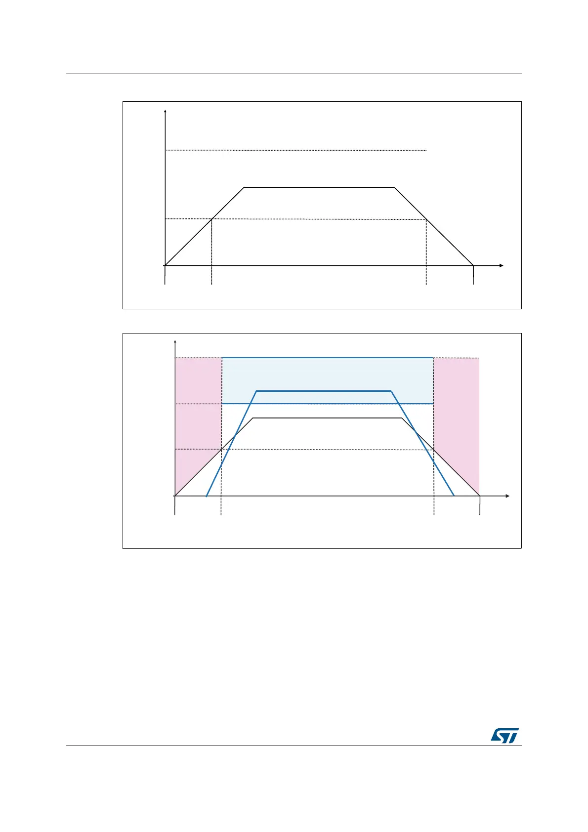
Figure 1. V
DDUSB
connected to V
DD
power supply
Figure 2. V
DDUSB
connected to external power supply.
In the STM32F7x3xx devices, the USB PHY HS sub-system uses an additional power
supply pin:
• The V
DD12OTGHS
pin is the output of the PHY HS regulator (1.2 V). An external
capacitor of 2.2 µF must be connected on the V
DD12OTGHS
pin.
Note: The PHY HS has another OTG_HS_REXT pin needed for calibration. This pin must be
connected to gnd via an external precise resistor (3
Kohm +/- 1%).
9
''B0,1
WLPH
9
''
9
''$
9
''86%
3RZHURQ
3RZHUGRZQ
2SHUDWLQJPRGH
9
''B0$;
9''
069
069
9
''86%B0,1
9
''B0,1
WLPH
9
''86%B0$;
86% IXQFWLRQDODUHD
9
''
9
''$
86% QRQ
IXQFWLRQDO
DUHD
9
''86%
3RZHURQ
3RZHUGRZQ
2SHUDWLQJPRGH
86%QRQ
IXQFWLRQDO
DUHD
 Loading...


