Recommended PCB routing guidelines for STM32F7 Series devices AN4661
44/54 DocID027559 Rev 5
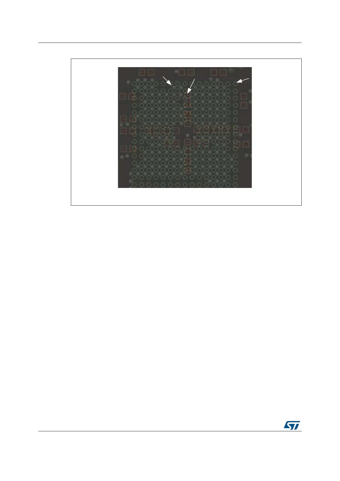
Figure 27. Example of bypass cap placed underneath the STM32F7 Series
• Place the bypass capacitors as close as possible to the power and ground pins of the
MCU.
• Add the recommended bypass capacitors for as many V
DD
/GND pairs as possible.
• Connect the bypass capacitor pad to the power and ground plane with a wider, short
trace/via to reduce the serie inductance, allow a maximum current flow and reduce the
transient voltage drops from the power plane. Which also reduces the possibility of
ground bounce.
8.4 High speed signal layout
8.4.1 SDMMC bus interface
Interface connectivity
The SD/SDIO MMC card host interface (SDMMC) provides an interface between the APB2
peripheral bus and Multi Media Cards (MMCs), SD memory cards and SDIO cards. The
SDMMC interface is a serial data bus interface, that consists of a clock (CK), command
signal (CMD) and 8 data lines (D[0:7]).
06Y9
sŝĂ
LJƉĂƐƐ
ĂƉ
'ďĂůů
 Loading...


